
Rapid phlegm suction device for emergency treatment
A rapid and emergency technology, applied in the direction of suction container, suction device, pumping and pumping system, etc., can solve the problems of poor sputum suction effect of sputum suction device, failure to clear blockage in time, difficulty in ensuring normal breathing, etc., to improve convenience and safety, saving medical resources and costs, and the effect of large negative pressure difference
Patent Information
- Authority / Receiving Office
- CN · China
- Current Assignee / Owner
- Publication Date
- 2019-07-19
Smart Images
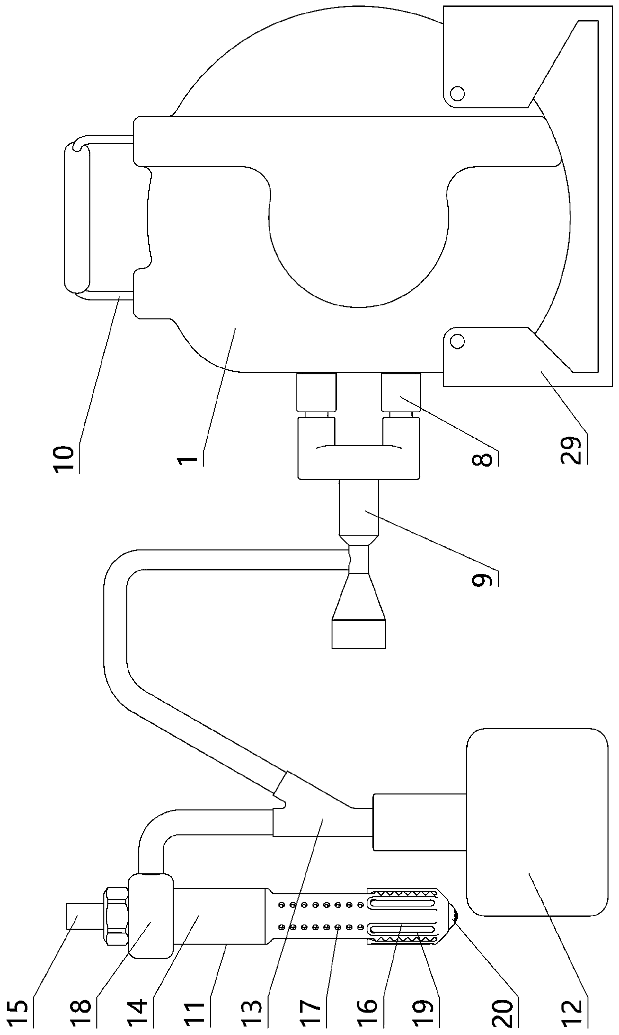
Figure 1 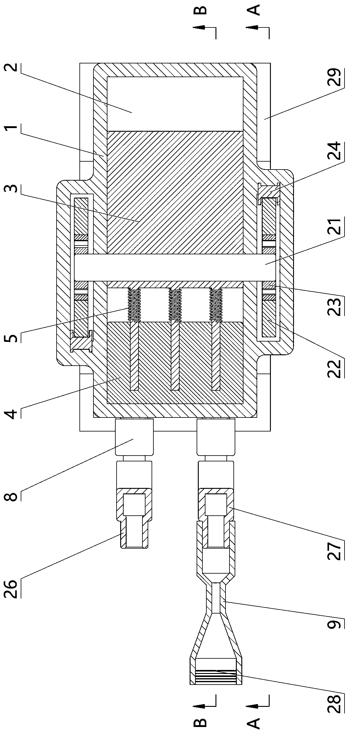
Figure 2 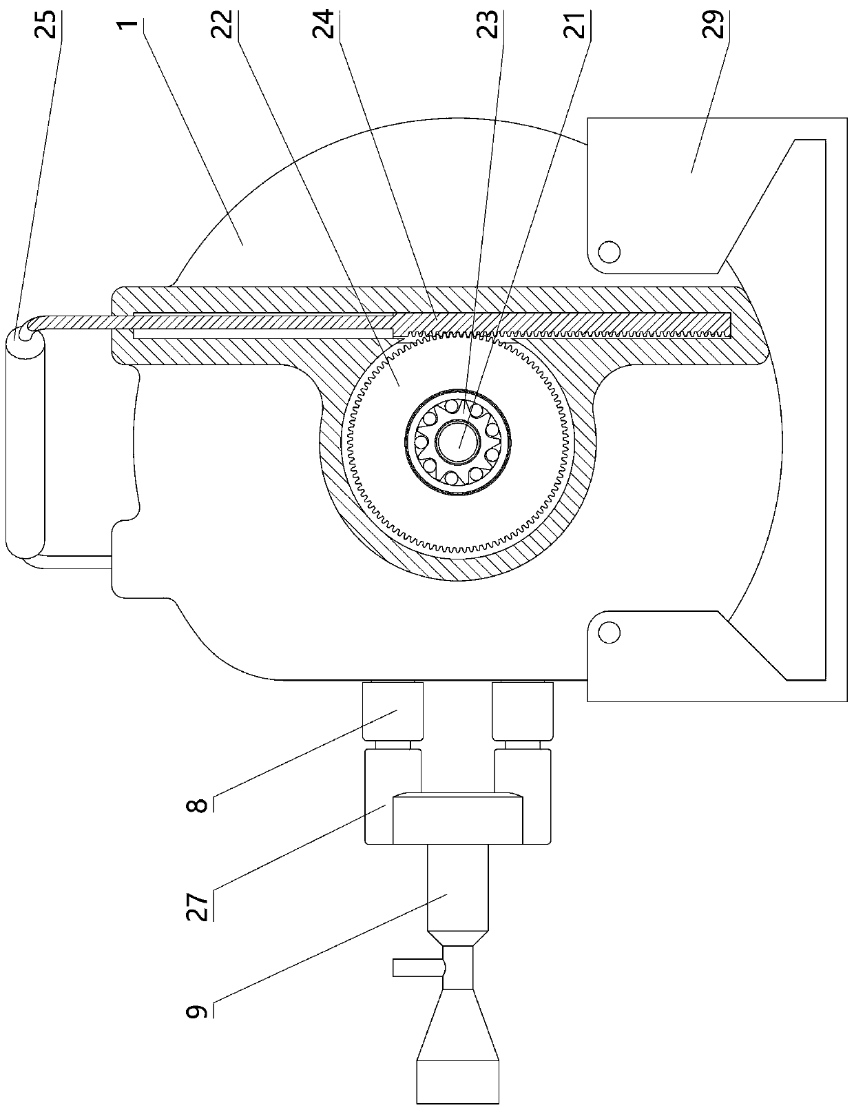
Figure 3
Abstract
Description
technical field
[0001] The present invention relates to emergency medical equipment, in particular to a rapid sputum suction device for emergency treatment. Background technique
[0002] In the process of emergency treatment, some emergency patients often encounter the problem of mucus blocking the airway due to various reasons, resulting in dyspnea. In this case, it is necessary to suck out the mucus in the patient's body as soon as possible to ensure normal breathing and prevent suffocation. Therefore, the emergency department usually has a sputum aspirator; however, the existing sputum aspirators are mainly electric multifunctional negative pressure sputum aspirators and simple manual sputum aspirators. It is more convenient to use in the consulting room. Once there is a power failure or when going out for first aid, it will be unusable, which will bring inconvenience to the rescue work; the simple manual sputum suction device does not need energy to drive, and uses the p...
Examples
Embodiment Construction
[0017] The specific implementation manners of the present invention will be described in further detail below in conjunction with the accompanying drawings.
[0018] Depend on Figure 1 to Figure 10 Given, the present invention is made up of suction device and intubation tube assembly, and described suction device comprises casing 1, and the cylindrical cavity 2 that axis is arranged front and rear on casing 1 and is placed in cylindrical cavity 2 and can be arranged along the column. The rotor 3 rotated by the axis of the shaped cavity 2, the front and rear end surfaces of the rotor 3 are attached to the front and rear end surfaces of the cylindrical cavity 2, and the left cavity wall of the cylindrical cavity 2 is a vertical plane and contacts the outer edge surface of the rotor 3; The rotor 3 described above has a left and right sliding horizontal partition 4 placed on the left side of the rotor 3, the left end of the horizontal partition 4 is in contact with the left wall ...