
Rotor of permanent magnet motor
A technology for permanent magnet motors and rotors, which is applied in the direction of magnetic circuit rotating parts, magnetic circuits, electrical components, etc., and can solve the unfavorable mass production of permanent magnet motor rotors, the need for thermal sleeves for interference fit, and the addition of key placement positions, etc. problem, to achieve the effect of saving heating equipment, stable and reliable installation, and conducive to mass production
Patent Information
- Authority / Receiving Office
- CN · China
- Patent Type
- Applications(China)
- Current Assignee / Owner
- Publication Date
- 2019-12-20
- Estimated Expiration
- Not applicable · inactive patent
Smart Images
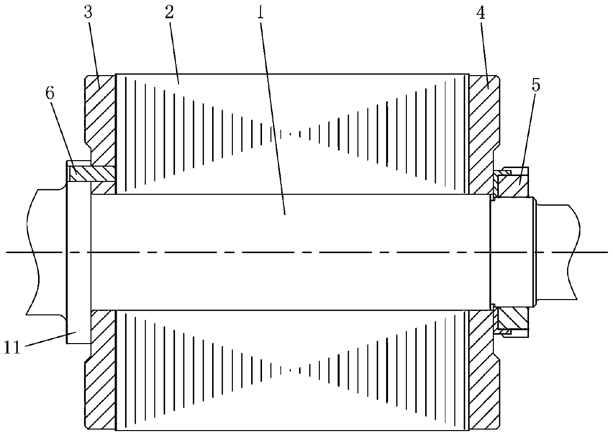
Figure 1
Abstract
Description
technical field
[0001] The invention relates to the technical field of permanent magnet motors, in particular to a rotor of a permanent magnet motor for new energy vehicles. Background technique
[0002] Due to the advantages of high power factor, high efficiency and small size of permanent magnet motor, its application value is more and more favored by the new energy automobile industry. Especially in recent years, all countries have vigorously advocated the development of the new energy automobile industry. With the support of various favorable national policies, permanent magnet motors will have immeasurable market application prospects. For new energy vehicles, both the governments of various countries and automobile manufacturers value them very much. It is only a matter of time before they replace fuel locomotives. Therefore, the market demand for permanent magnet motors has risen sharply in recent years. How to design permanent magnet motors with simple structure, hig...
Examples
Embodiment Construction
[0016] The present invention will be described in further detail below in conjunction with the accompanying drawings and specific embodiments.
[0017] Such as figure 1 As shown, the rotor of the permanent magnet motor in this embodiment includes a rotating shaft 1 and a rotor core 2 sleeved on the rotating shaft 1, and a first rotor end plate 3 and a second rotor end plate 4 are installed on the rotating shaft 1. The rotor end plate 3 and the second rotor end plate 4 are separately arranged at both ends of the rotor core 2 and are clamped to fix the rotor core 2. The first rotor end plate 3 and the second rotor end plate 4 are sleeved on the rotating shaft 1, and the second Both the first rotor end plate 3 and the second rotor end plate 4 are in clearance fit with the rotating shaft 1, and the rotating shaft 1 is provided with a blocking portion 11, one end of the first rotor end plate 3 is in contact with the blocking portion 11, and the other end of the first rotor end plat...