
A vibrating guide brick for the blind
A guiding brick and vibrating technology, applied in the field of vibrating blind road guiding bricks, can solve the problems of insignificant guiding effect and poor comfort, and achieve the effects of preventing deviation, reducing soreness and improving practicability.
Patent Information
- Authority / Receiving Office
- CN · China
- Patent Type
- Patents(China)
- Current Assignee / Owner
- Publication Date
- 2021-06-22
Smart Images
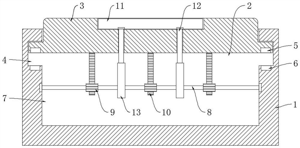
Figure 1 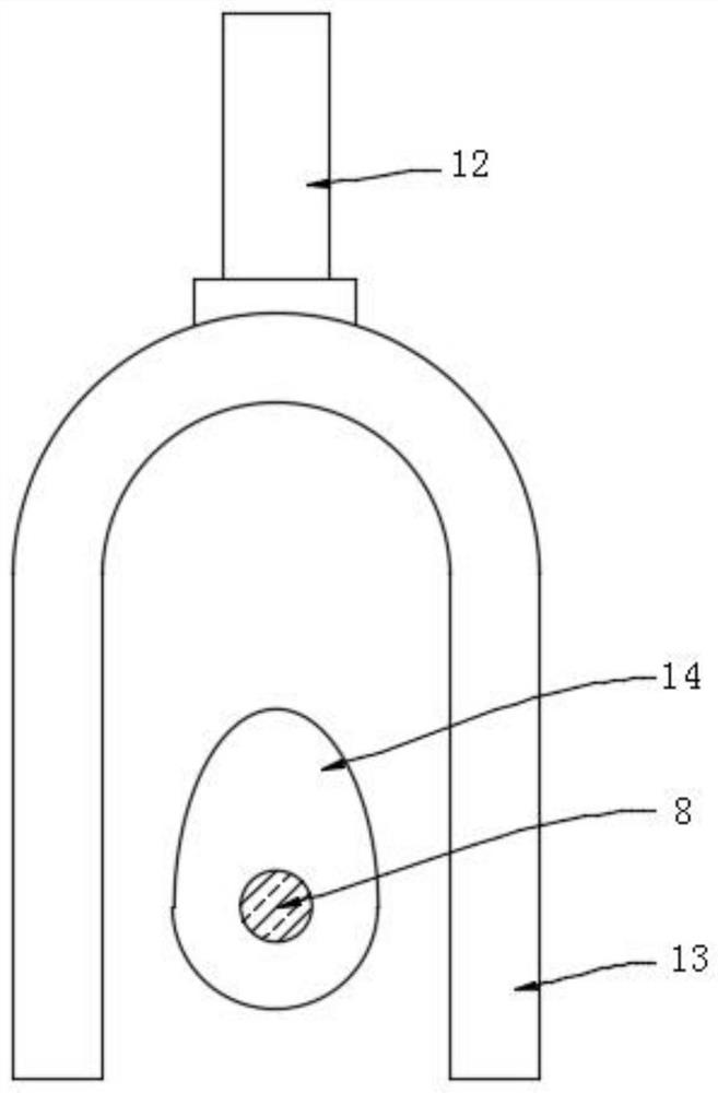
Figure 2 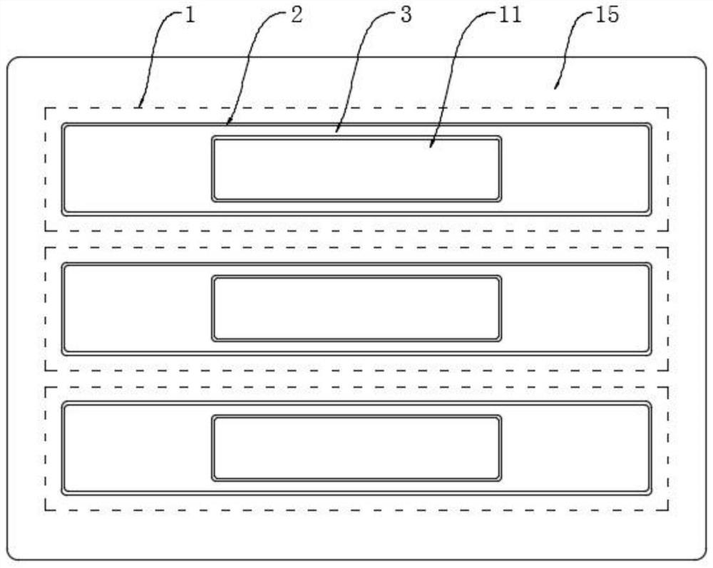
Figure 3
Abstract
Description
technical field
[0001] The invention relates to the technical field of municipal construction, in particular to a vibrating blind road guide brick. Background technique
[0002] The blind path is a road facility specially designed to help blind people walk. The guide is a kind of brick with straight strips of protrusions, which are used to pave the blind path. The straight strips point to the direction of the blind path, that is, when walking along the straight strips. The protrusion can make the blind stick and the sole of the foot feel, and it is convenient to guide the visually disabled to walk forward in a straight line safely.
[0003] However, the bulges on the surface of traditional tactile floor tiles are generally hard. When a blind person walks on the tactile path for a long time, it is easy to cause sore muscles on the soles of the feet, which brings pain to the blind person and is not convenient for the blind person to walk. The tactile sensitivity decreases, wh...
Examples
Embodiment 1
[0022] refer to Figure 1-3 , a vibrating blind path guide brick, comprising a brick body 1, a plurality of chutes 2 are uniformly opened in parallel on the brick body 1, each chute 2 is slidably connected with a guide strip 3, and the side wall of each chute 2 Limiting grooves 4 are provided on the top, and the edge of each guiding strip 3 extends into the corresponding limiting groove 4. The lower end of each guiding strip 3 is embedded with a first magnetic ring 5, and the bottom side of each limiting groove 4 The walls are all embedded with a second magnetic ring 6, and the first magnetic ring 5 is the same as the magnetic pole on the opposite side of the corresponding second magnetic ring 6, then the guide bar 3 is under the repulsive force of the first magnetic ring 5 and the second magnetic ring 6 Its side wall is offset against the upper groove wall of the limiting groove 4, and the height difference between the upper end surface of the guide strip 3 and the horizontal...
Embodiment 2
[0027] refer to Figure 4 , the difference between this embodiment and Embodiment 1 is that: the upper end surface of the brick body 1 is embedded with a ring-shaped light strip 15, and the ring-shaped light strip 15 can be made of LED lamp beads, and the LED lamp beads only need a small current. It can be lighted, and two micro-generators 16 are symmetrically arranged on the groove wall of the installation groove 7. The micro-generators 16 are alternators, and the input shafts of the two micro-generators 16 are welded to the two ends of the rotating rod 8 respectively. , the output ends of the two micro-generators 16 are electrically connected to the ring-shaped light strip 15 through wires.
[0028] In this embodiment, when the gear 9 drives the rotating rod 8 to rotate, and the rotating rod 8 drives the input shaft of the micro-generator 16 to rotate, the micro-generator 16 generates alternating current and transmits it to the ring-shaped light strip 15 through the wire, an...