
A brushless power feedback permanent magnet speed control device combining axial and radial magnetic flux
A technology of radial magnetic flux and permanent magnet speed regulation, applied in electromechanical devices, magnetic circuit shape/style/structure, permanent magnet clutch/brake, etc., can solve the problem of reducing the torque density and speed regulation of permanent magnet governors The efficiency of the device is low, the strength of the air gap magnetic field is weakened, etc., so as to improve the space utilization rate, solve the heat dissipation problem, and improve the operation efficiency.
Patent Information
- Authority / Receiving Office
- CN · China
- Patent Type
- Patents(China)
- Current Assignee / Owner
- Publication Date
- 2021-03-16
Smart Images
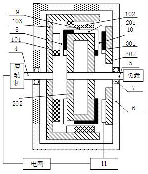
Figure 1 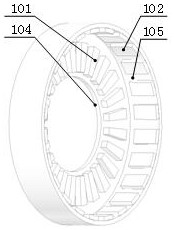
Figure 2 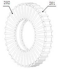
Figure 3
Abstract
Description
technical field
[0001] The invention relates to a permanent magnet governor, in particular to a brushless power feedback type permanent magnet governor combined with axial and radial flux. Background technique
[0002] With the promotion and application of high-performance permanent magnet materials, the permanent magnet speed control technology, which has developed rapidly, is a new type of speed control and energy-saving technology for motor drive systems applied between the prime mover and the load. The speed-regulating permanent magnet coupler has a good energy-saving effect, reduces operating costs, and can also realize the soft start and soft stop functions of the motor. It can operate in harsh environments such as flammable, explosive, humid, and high dust content, and it is a mechanical structure that can adapt to situations such as unstable power grid quality and impact loads caused by current changes. Mainly used in the chemical industry, petrochemical industry, c...
Examples
Embodiment Construction
[0026] The technical solution of the present invention will be further described below in conjunction with the accompanying drawings.
[0027] Such as figure 1 As shown, a brushless power feedback type permanent magnet speed regulating device with axial and radial flux combined, the device mainly includes a permanent magnet speed governor with axial and radial flux combined and a slip power feedback control unit. The permanent magnet governor includes a concentrically installed permanent magnet rotor, a conductor rotor and a three-phase winding stator; the permanent magnet rotor is fixed on the input shaft 4 and connected to the prime mover, and the conductor rotor is fixed on the output shaft 5 and connected to the load , the three-phase winding stator is fixed together with the casing 6, and is connected with the output shaft 5 through the bearing 7; The inner side of the magnetic rotor back iron core 103 is formed; the conductor rotor is composed of a bent three-phase con...