
Shaping equipment
An equipment and plate technology, applied in the field of plastic forming equipment that can elastically reshape plates, can solve the problems of lowering the overall yield, lack of plate elasticity, damage to the plate by the contact area, etc., to increase the convenience of operation, improve the quality rate effect
Patent Information
- Authority / Receiving Office
- CN · China
- Current Assignee / Owner
- Publication Date
- 2020-05-01
Smart Images
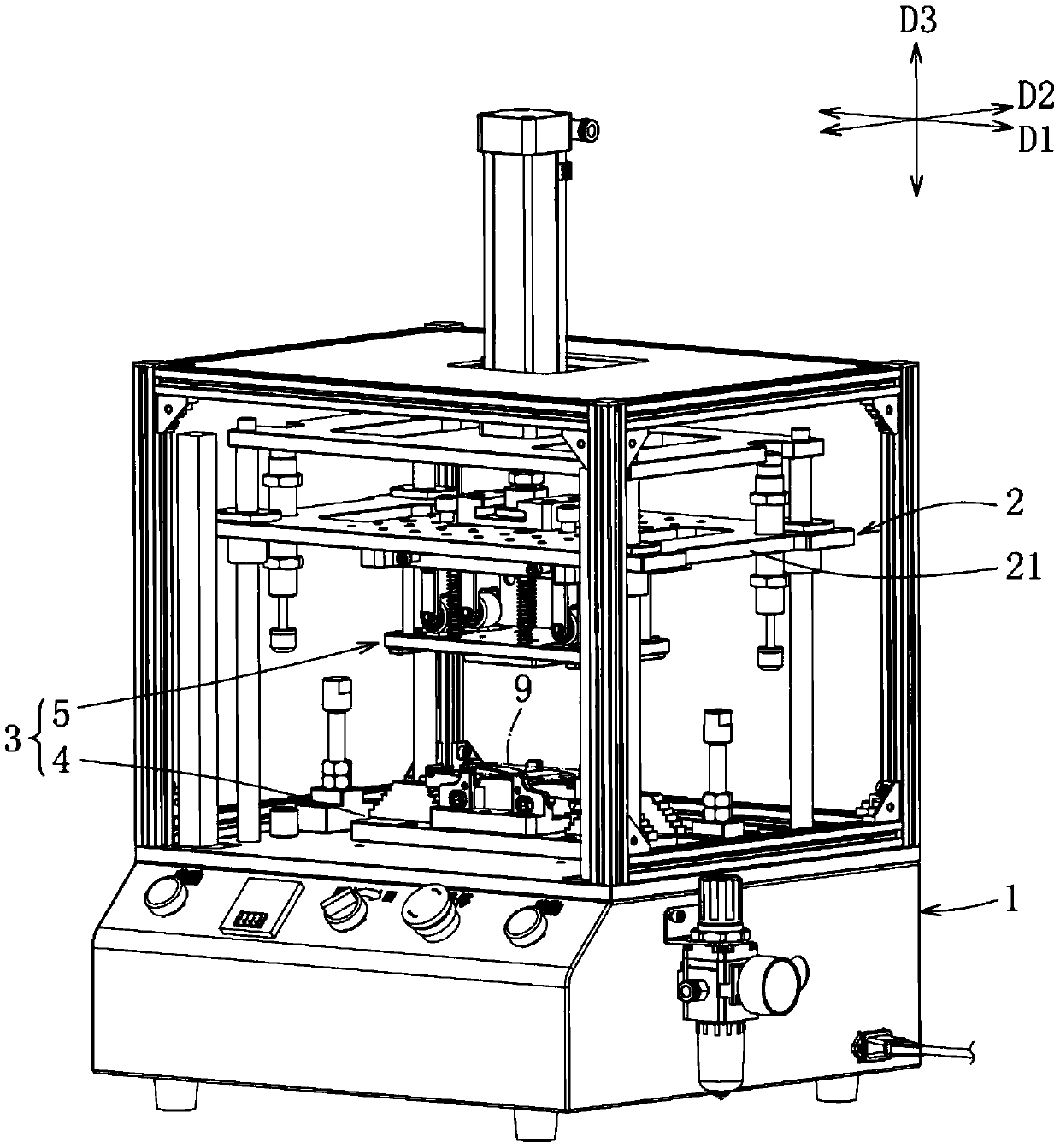
Figure 1 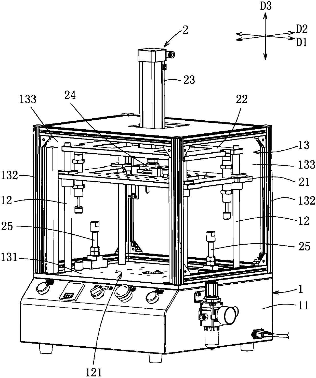
Figure 2 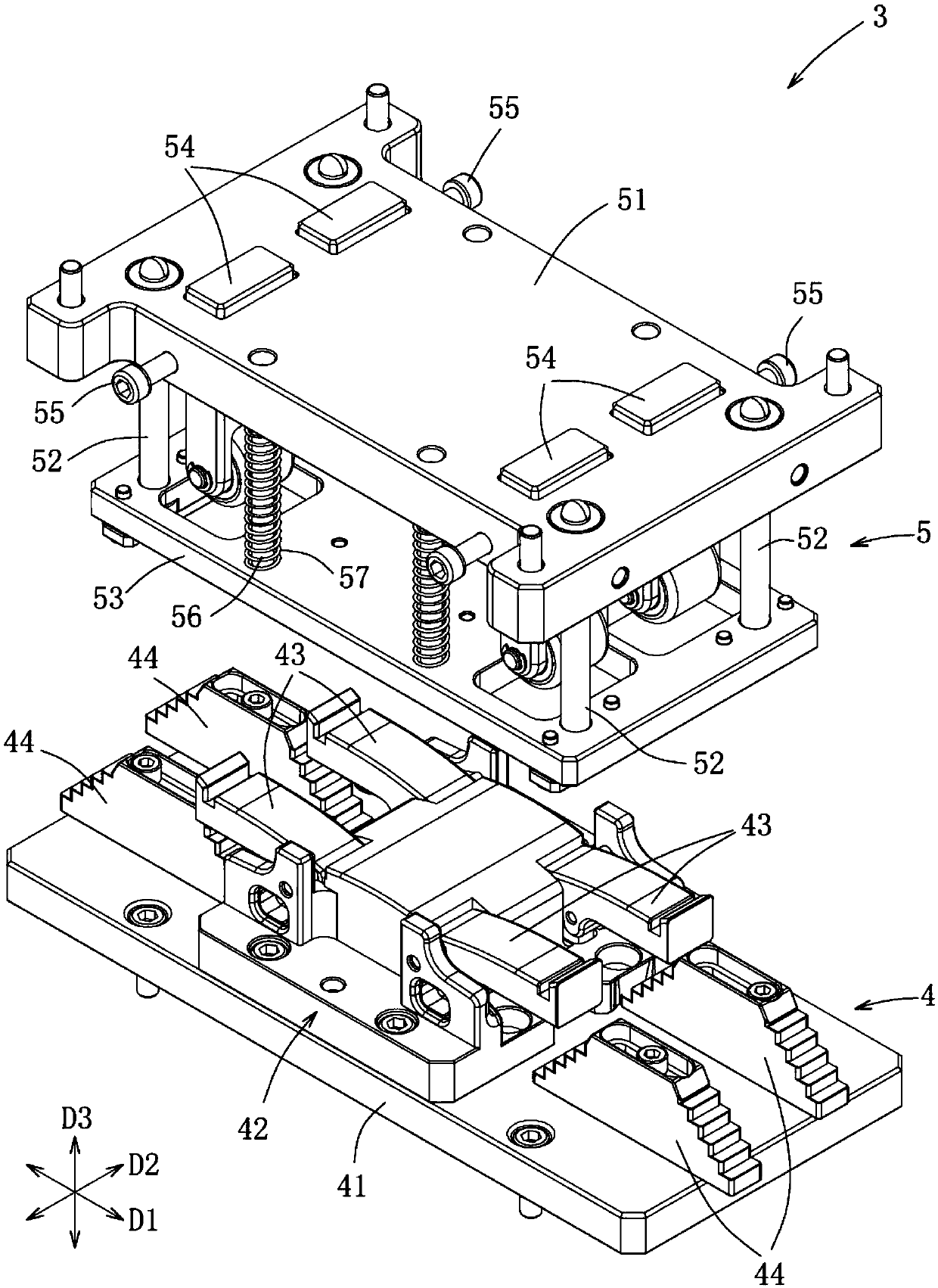
Figure 3
Abstract
Description
technical field
[0001] The invention relates to a shaping device, in particular to a shaping device capable of elastically shaping a plate. Background technique
[0002] The existing plate shaping uses a shaping block and a pressing block as a shaping mold. By setting the plate to be shaped on the workbench, a driving device is used to push the pressing block and exert pressure together with the shaping block. For the board, such as a mobile phone casing.
[0003] For example, Chinese Patent Publication No. CN106142522A discloses a shape-setting tool for plastic parts. The shape-setting tool mainly includes a workbench, shaping blocks, multiple guide rods and a hydraulic control system. block, moving plate and fixed plate, and the pressing block exerts pressure on the plate placed on the shaping block through the hydraulic control system to achieve the purpose of shaping.
[0004] However, the pressing block of the above-mentioned conventional shaping tool is used to shape...
Examples
Embodiment Construction
[0038] refer to figure 1 , an embodiment of the molding equipment of the present invention for molding a plate 9 , the molding equipment includes a carrier 1 , a driving device 2 and a pressing device 3 . In this embodiment, the plate 9 is, for example, a mobile phone case, but not limited to the mobile phone case, as long as the plate 9 is made of ductile material, it can be processed by shaping equipment.
[0039] refer to figure 1 and figure 2 The stage 1 includes a control base 11 , four inner brackets 12 surrounding the top surface of the control base 11 for the drive device 2 to install, and a shielding unit 13 surrounding the inner bracket 12 and forming a forward opening 131 . The inner frame 12 jointly defines a working area 121 for the driving device 2 and the pressing device 3 to perform mechanical actions. In addition, the shielding unit 13 has four outer frames 132 surrounding the inner frame 12 and a plurality of shields 133 connected to the outer frames 132 ...