
Forced centering device for precision engineering measurement
A technology of forced centering and precision engineering. It is used in measuring devices, measuring instruments, surveying and mapping, and navigation. It can solve the problems of difficulty in opening again, inconvenient disassembly and assembly, and inability to adjust the structure again, so as to increase stability and ensure stability. Effect
Patent Information
- Authority / Receiving Office
- CN · China
- Patent Type
- Applications(China)
- Current Assignee / Owner
- Publication Date
- 2020-08-18
Smart Images
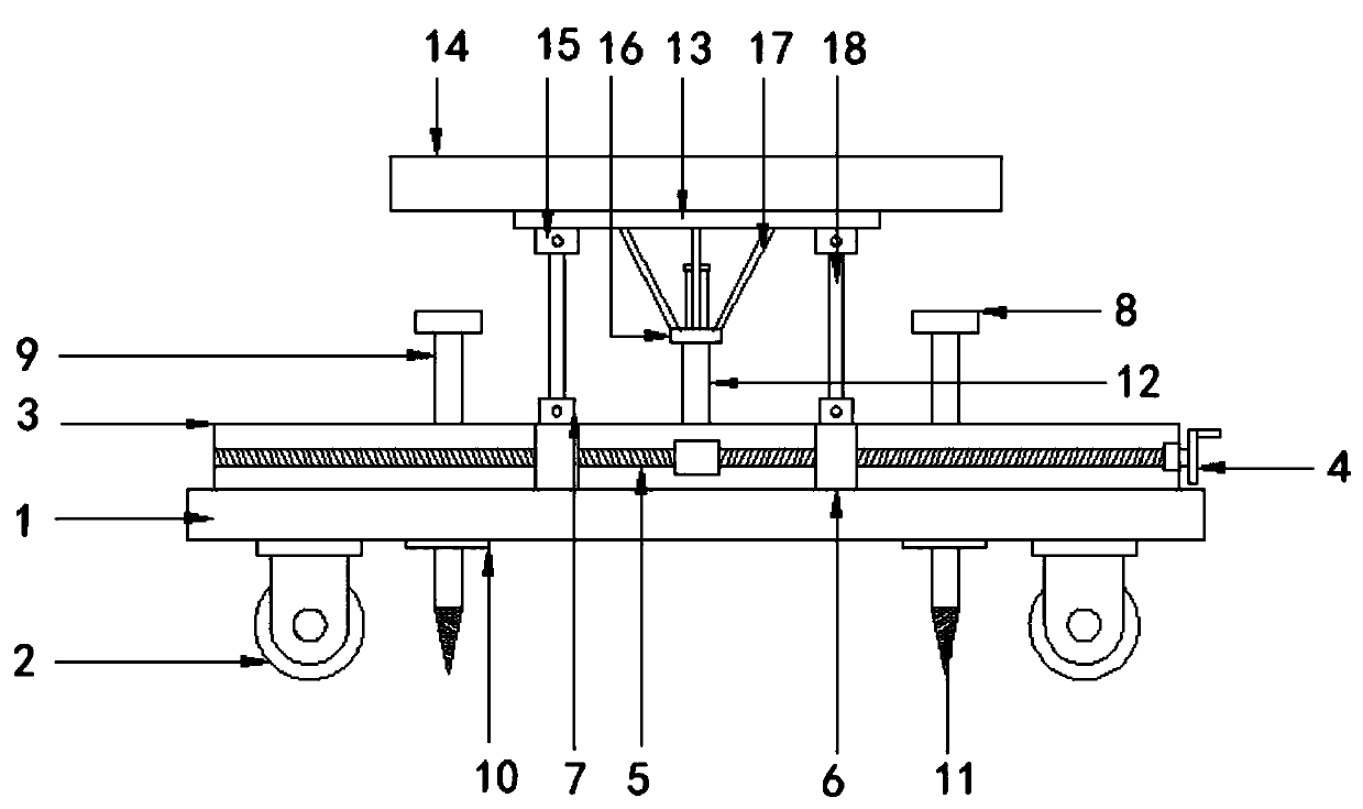
Figure 1 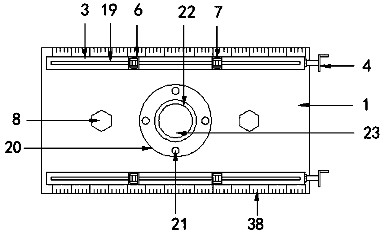
Figure 2 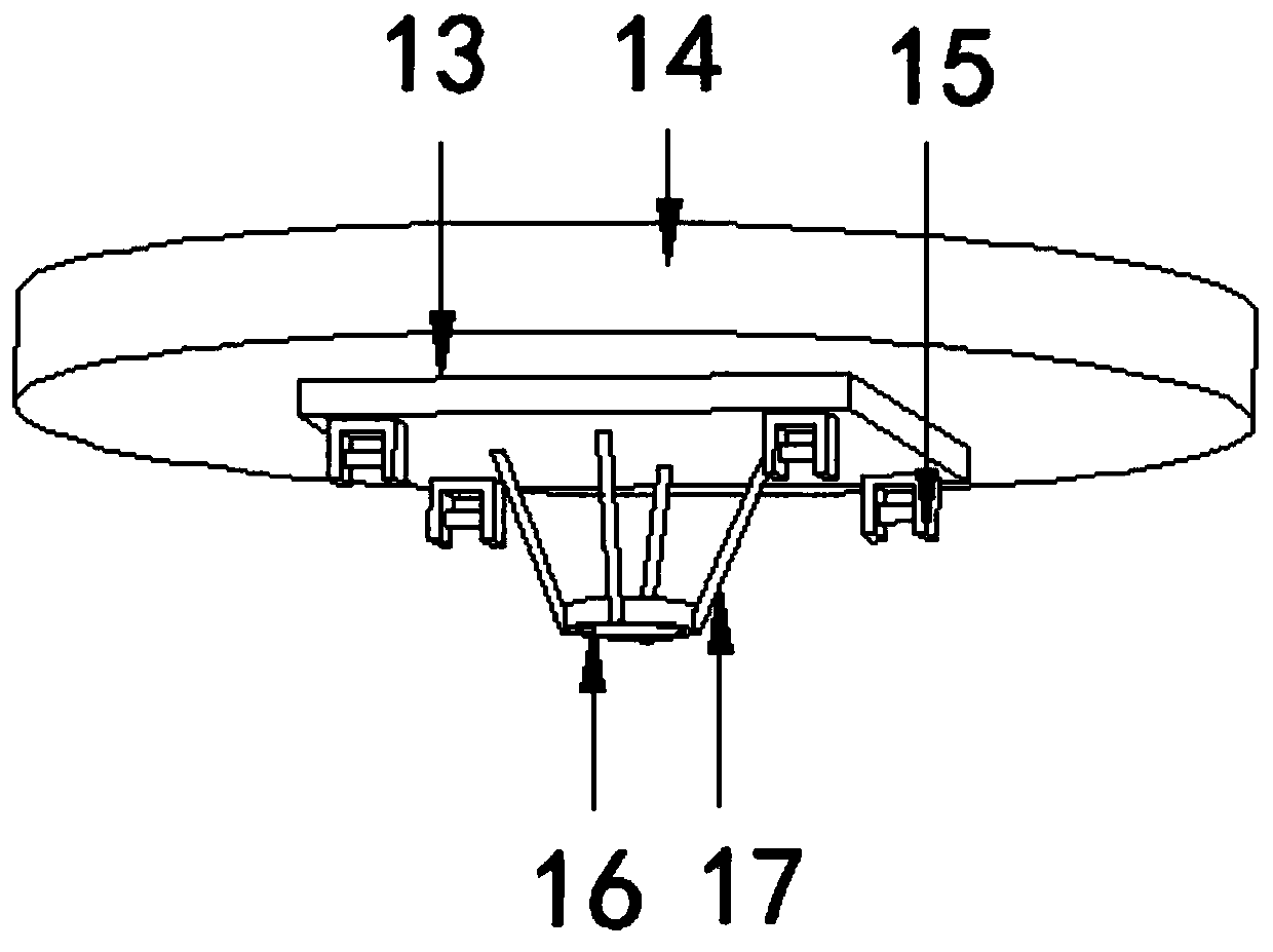
Figure 3
Abstract
Description
technical field
[0001] The invention relates to the technical field of engineering measurement, and more specifically relates to a forced centering device for precision engineering measurement. Background technique
[0002] Engineering survey is an important part of engineering construction, including control survey and topographic survey in the planning and design stage, construction survey, equipment installation survey and completion survey in the construction stage, deformation survey in the operation and management stage, etc. For large-scale projects and special projects, such as railways, tunnels, mines, bridges, and national defense projects, precision engineering measurement is required to meet the high standard requirements of engineering construction, positioning or deformation observation. In order to ensure the high precision of the observation data and the reliability of the results, precision engineering surveys generally do not use traditional temporary tripo...
Examples
Embodiment Construction
[0024] The following will clearly and completely describe the technical solutions in the embodiments of the present invention with reference to the accompanying drawings in the embodiments of the present invention. Obviously, the described embodiments are only some, not all, embodiments of the present invention. Based on the embodiments of the present invention, all other embodiments obtained by persons of ordinary skill in the art without making creative efforts belong to the protection scope of the present invention.
[0025] see Figure 1-7 , the present invention provides a technical solution: a forced centering device for precision engineering measurement, comprising: a fixed plate 1, a box body 3 is provided on the upper part of the fixed plate 1 and two groups of boxes are provided on the box body 3, and the box body 3 They are parallel to each other and installed on the upper and lower ends of the fixed plate 1. The inside of the box body 3 is provided with a screw rod...