
Elastic self-locking full roller bearing and robot reduction gear thereof
A full-roller, elastic technology, applied in the field of elastic self-locking full-roller bearings and their robot reducers, can solve the problems of scattered rollers, inner rings and outer rings, reduced bearing performance, not standard parts, etc. Achieve the effect of preventing roller skew, reducing axial force and low processing cost
Patent Information
- Authority / Receiving Office
- CN · China
- Patent Type
- Applications(China)
- Current Assignee / Owner
- Publication Date
- 2020-09-22
Smart Images
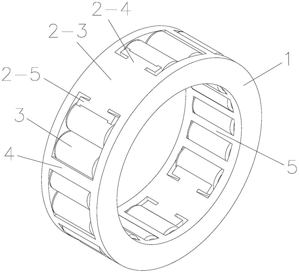
Figure 1 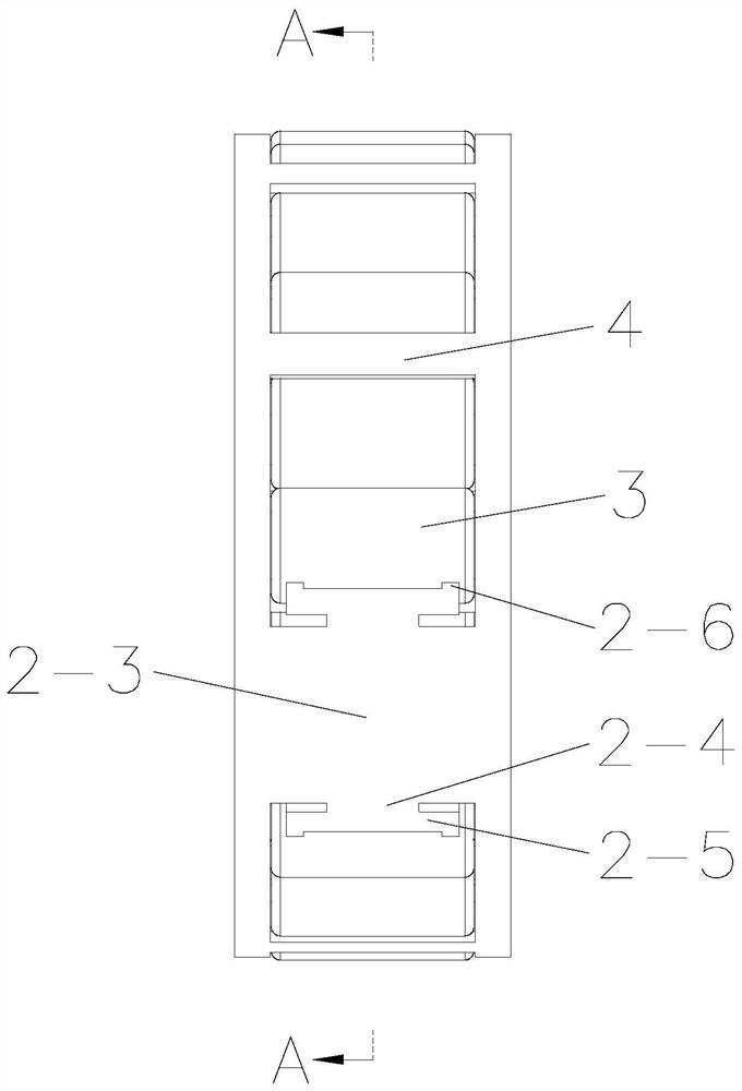
Figure 2 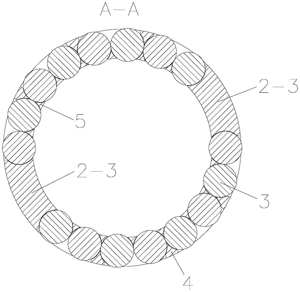
Figure 3
Abstract
Description
technical field
[0001] The invention relates to the technical field of self-locking full roller bearings, in particular to an elastic self-locking full roller bearing and a robot reducer thereof. Background technique
[0002] The bearing composed of the radial roller and the cage assembly used in the robot reducer has a large market in some bearing application fields because of its high rotation accuracy and large load. However, due to the limited space inside the bearing, its structural form is usually There are "M" type cage and roller assembly structure, "door" shedding type cage and roller assembly structure, inner and outer plastic sleeve full complement roller structure without cage. In the case of limited installation space, the existing full roller bearings generally do not have a cage, and the rollers are directly inserted between the two components during use. However, the full complement roller structure without a cage is used The inner and outer plastic sleeves ...
Examples
Embodiment 1
[0040] Such as Figure 1-Figure 5 The shown elastic self-locking full roller bearing includes a cage, and the cage includes two ring-shaped baffles 1, and also includes an elastic main beam, which includes a beam body 2-3, and a beam body 2- 3 Connected between two baffles 1, the two ends of the beam body 2-3 are respectively fixedly installed with the first elastic body and the second elastic body, and the space between the first elastic body and the second elastic body is fully filled with rollers 3 , the elastic main beam is used to adjust the circumferential gap between the rollers 3, so that two adjacent rollers 3 are set in contact.
[0041] Both the first elastic body and the second elastic body include a connecting block 2-4 and an elastic plate 2-5, the connecting block 2-4 connects the beam body 2-3 and the elastic plate 2-5, and the two ends of the elastic plate 2-5 extend Out of the connection block 2-4, the two ends of the elastic plate 2-5 are fixedly equipped w...
Embodiment 2
[0047] Such as Image 6 As shown, the difference between Embodiment 2 and Embodiment 1 is only that the elastic main beam has a single baffle plate with several rollers 3 evenly distributed between the first guide surface 2-1 and the second guide surface 2-2. 1 circle.
Embodiment 3
[0049] Such as Figure 7 with Figure 8 Compared with Embodiment 1, the shown embodiment 3 differs only in that: in order to realize that the rollers 3 are fully filled between the first guide surface 2-1 and the second guide surface 2-2, the outer lock 4 on the cage The number of -1 is consistent with the number of rollers 3 and corresponds one by one. The number of inner locks 5-1 on the cage is half of the number of outer locks 4-1, and the number of inner locks 5-1 is used to limit two The roller 3, the outer lock 4-1, the first limiting pocket 6 and the second limiting pocket 7 are all used to limit a single roller 3. Use two baffles 1 to axially fix the roller 3 to reduce the axial force during the operation of the bearing. The outer side of the roller 3 is limited by the outer lock 4-1 to prevent it from falling out of the pocket hole. The inner side of the child 3 is limited by the inner lock 5-1 to prevent it from falling out of the pocket, wherein the inner lock 5-...