
Vertical Differential Velocity Measuring Method of Test Pull Coordinate System
A technology of coordinate system and test piece, applied in the field of optical measurement, can solve problems such as low efficiency, time-consuming, affecting detection and production progress, etc., and achieve the effect of high reliability, accurate method, and meeting the precision requirements of the machine itself
Patent Information
- Authority / Receiving Office
- CN · China
- Patent Type
- Patents(China)
- Current Assignee / Owner
- Publication Date
- 2022-03-04
Smart Images
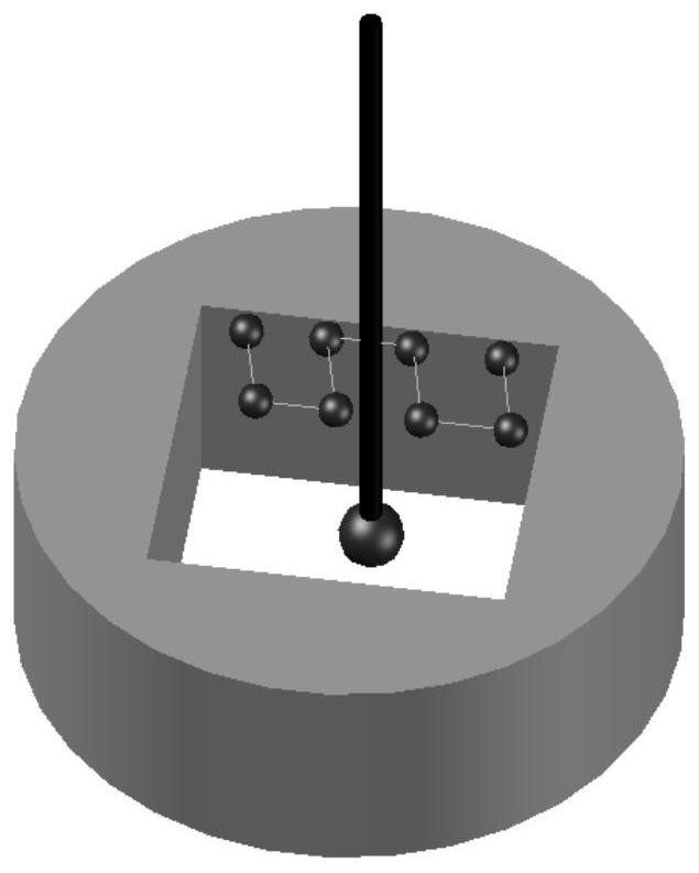
Figure 1 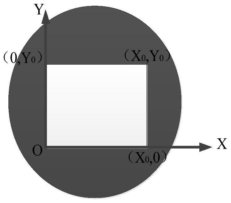
Figure 2 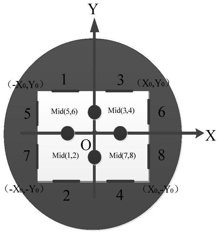
Figure 3
Abstract
Description
technical field
[0001] The invention relates to the field of optical measurement, in particular to a method for measuring vertical differential velocity of a coordinate system of a test piece. Background technique
[0002] The vertical difference of the cage pockets is a key characteristic that affects the quality and life of the bearing, and it is related to whether the rollers can run normally in the bearing. When machining the cage pocket, the broach is used for broaching, so detecting the vertical difference of the test piece is an indirect measurement method to verify whether the vertical difference of the broach is qualified. In the past, when measuring the vertical difference of the test piece, the probe was used to measure the plane, and each sample of the same model had to repeat this step. Although this method can ensure the accuracy of the measured value, it takes a long time and has low efficiency, which seriously affects the detection and production progress. ...
Examples
specific Embodiment approach 1
[0036] Specific embodiment one: the vertical differential velocity measuring method of test pull piece coordinate system, it comprises the following steps:
[0037] Step 1: Fix the workpiece on the three-dimensional optical measuring instrument,
[0038] Step 2: Optically position the workpiece and set up a coordinate system,
[0039] Use any right angle in the square hole in the middle of the workpiece as the starting position of the coordinate system to locate and establish the coordinate system;
[0040] Step 3: Manually call the probe mode to measure the vertical difference of the workpiece,
[0041] Call the probe, manually measure four points on the rectangular plane of the square hole in the middle of the workpiece, determine the measured range of the measuring surface, use the three-dimensional optical measuring instrument to build a rectangular grid, and the machine will automatically distribute the measurement in the form of a grid within the determined range of the...
specific Embodiment approach 2
[0044] Specific implementation mode two: the specific process of setting up the coordinate system in the step two is as follows: two right-angled sides extending at right angles from the starting position are used as reference lines, one is used as the X axis, and the other is used as the Y axis; Point fitting plane, set the Z axis to be perpendicular to the plane.
[0045] Other implementation manners are the same as the specific implementation manner 1.
specific Embodiment approach 3
[0046] Embodiment 3: The process of building a rectangular network of the three-dimensional optical measuring instrument in step three is: using the automatic measurement path and coordinate grid function of the three-dimensional optical measuring instrument to construct.
[0047] Other implementation manners are the same as the specific implementation manner 1.