
Novel bearing laser marking machine
A laser marking machine and bearing technology, applied in the field of laser marking, can solve the problems of inconvenient bearing clamping, inability to turn over the work seat, inconvenient positioning function of the clamping frame, etc., and achieve the effect of convenient turning
Patent Information
- Authority / Receiving Office
- CN · China
- Current Assignee / Owner
- Publication Date
- 2020-09-25
- Estimated Expiration
- Not applicable · inactive patent
Smart Images
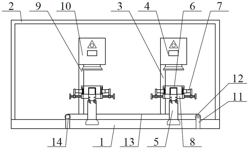
Figure 1 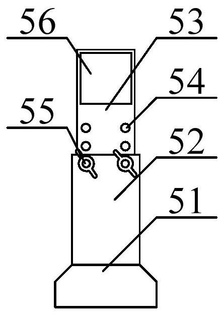
Figure 2 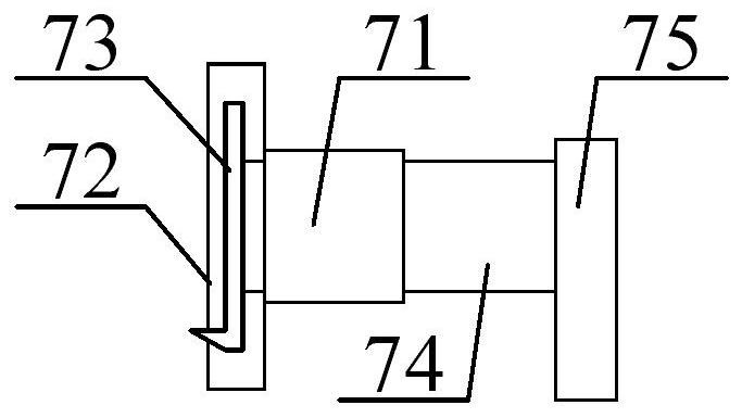
Figure 3
Abstract
Description
technical field
[0001] The invention belongs to the technical field of laser marking, in particular to a novel bearing laser marking machine. Background technique
[0002] The DATAMATRIX two-dimensional barcode recognition technology is used in the former pair of bearing parts. Each set of bearings has a unique two-dimensional code and clear code, which records the bearing supplier, bearing code, production date, production line, product serial code, etc. Information, at present, the laser is used to mark the two-dimensional code on the large end face of the bearing, and the laser marks the clear code on the small end face of the bearing, and the two are mutually unified.
[0003] However, the existing laser marking machines for bearings have the problems of not being able to turn over the work seat according to the requirements, inconveniently clamping the bearing and inconveniently positioning the clamping frame.
[0004] Therefore, it is very necessary to invent a new be...
Examples
Embodiment Construction
[0029] The present invention will be further described below in conjunction with accompanying drawing:
[0030] as attached figure 1 And attached Figure 4 As shown, a new type of bearing laser marking machine according to the present invention includes a horizontal bottom plate 1, an installation shell 2, a right side bracket 3, a right side laser marking machine 4, an adjustable rotating bracket structure 5, and a bearing storage frame 6. Bearing positioning and fixing frame structure 7, rotating clamping frame structure 8, left bracket 9, left laser marking machine 10, side plate 11, conveying roller 12, conveying belt 13 and conveying motor 14, the installation The casing 2 screws are installed on the outer upper part of the transverse base plate 1; the right side bracket 3 bolts are installed on the upper right side of the transverse base plate 1; the right side laser marking machine 4 bolts are installed on the upper side of the right side bracket 3 The adjustable rota...