
Dehumidification type waterproof floor tile
A dehumidification type, floor tile technology, applied in the field of floor tiles, can solve the problems of not being able to quickly self-clean and the floor tiles are prone to water and moisture, etc., to reduce the probability of slipping, speed up drainage, and avoid the effects of water accumulation
Patent Information
- Authority / Receiving Office
- CN · China
- Patent Type
- Applications(China)
- Current Assignee / Owner
- Publication Date
- 2020-11-03
Smart Images
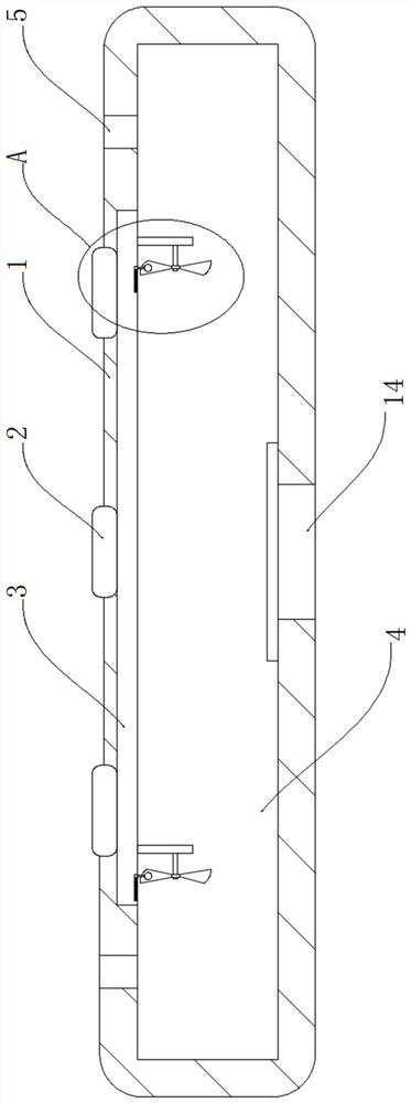
Figure 1 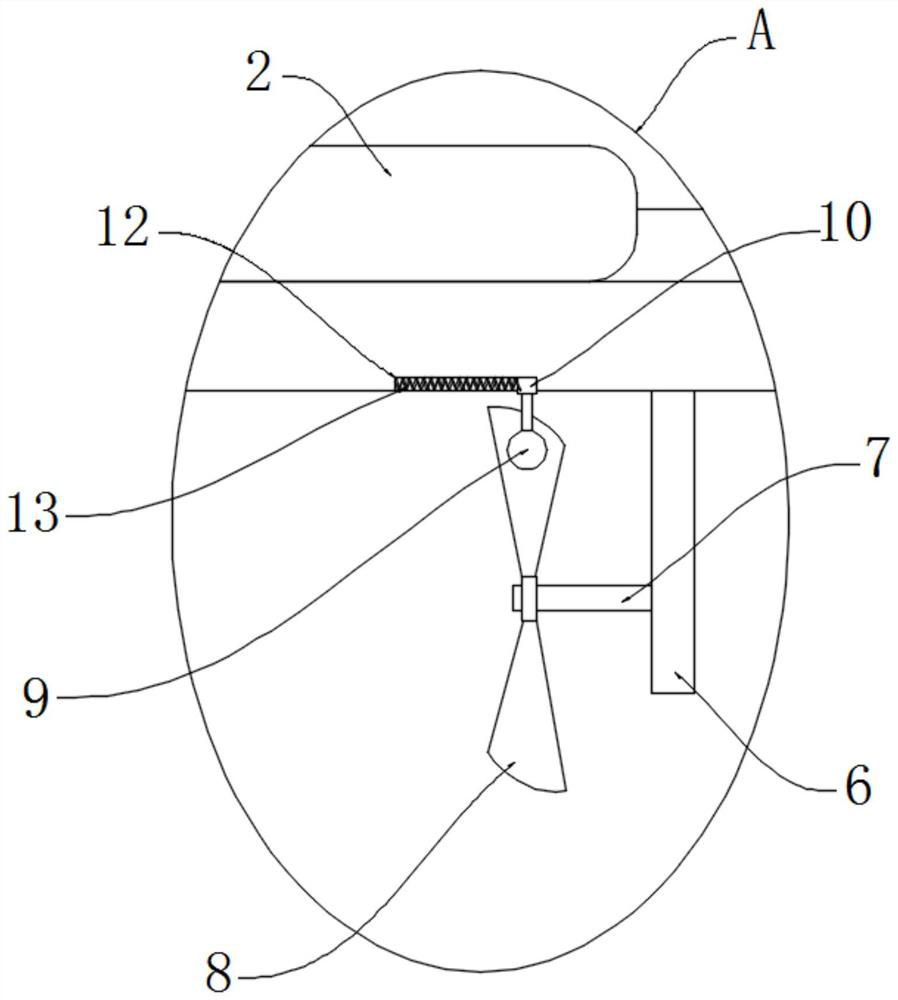
Figure 2
Abstract
Description
technical field
[0001] The invention relates to the technical field of floor tiles, in particular to a dehumidifying waterproof floor tile. Background technique
[0002] Floor tiles are a kind of floor decoration material, also called floor tiles. Most floor tiles are fired from clay and can be divided into various specifications and styles. They have the advantages of firm quality, pressure resistance and wear resistance, and moisture resistance. Some After glazing treatment, it has a decorative effect and is mostly used for the ground and floor of public buildings and civil buildings.
[0003] When the pavement floor tiles in the prior art are in use, especially when using smooth surface floor tiles in shopping malls and streets, etc., they are easily polluted by water, so that the water left on the surface reduces the friction coefficient of the floor tile surface, so that when people walk It is easy to fall down and does not have the effect of quick water removal. Based...
Examples
Embodiment
[0019] refer to Figure 1-2 , a dehumidification type waterproof floor tile, comprising a brick body 1, a plurality of flexible pedals 2 are embedded on the upper surface of the brick body 1, the plurality of flexible pedals 2 are arranged in a circular array and the bottom is jointly attached and connected with a piezoelectric ceramic plate 3, the brick There is a liquid storage chamber 4 inside the body 1, and the bottom of the piezoelectric ceramic plate 3 runs through the liquid storage chamber 4, and the top of the liquid storage chamber 4 is provided with two liquid inlet holes 5, and the two liquid inlet holes 5 are located on the symmetrical sides of the brick body 1. On both sides, a liquid outlet is opened at the bottom of the liquid storage chamber 4 and a pressure valve 14 is sealingly connected to the liquid outlet;
[0020] The piezoelectric ceramic plate 3 is electrically connected with a plurality of fixed plates 6, and each fixed plate 6 is provided with a tor...