
Main shaft device capable of adjusting length of wire bow
A technology of spindle device and line adjustment, which is applied in the direction of grinding machine parts, grinding machines, metal processing equipment, etc., can solve the problem of waste of resources, and achieve the effect of reducing the length of the wire bow and expanding the range of the length of the wire bow.
Patent Information
- Authority / Receiving Office
- CN · China
- Patent Type
- Applications(China)
- Current Assignee / Owner
- Publication Date
- 2020-11-06
- Estimated Expiration
- Not applicable · inactive patent
Smart Images
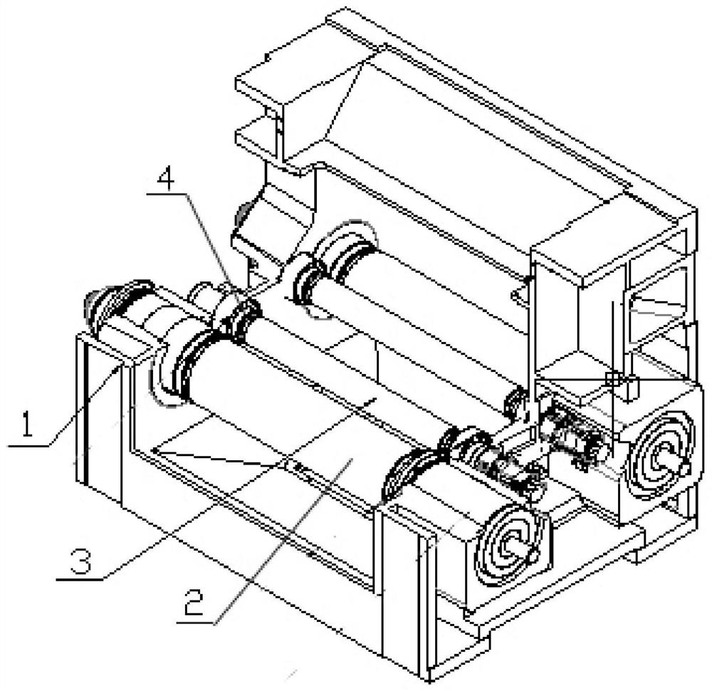
Figure 1 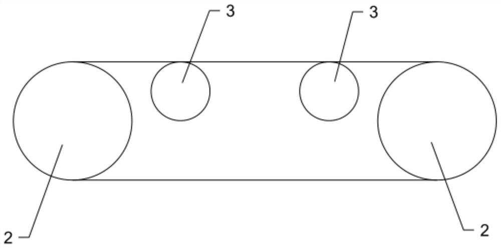
Figure 2 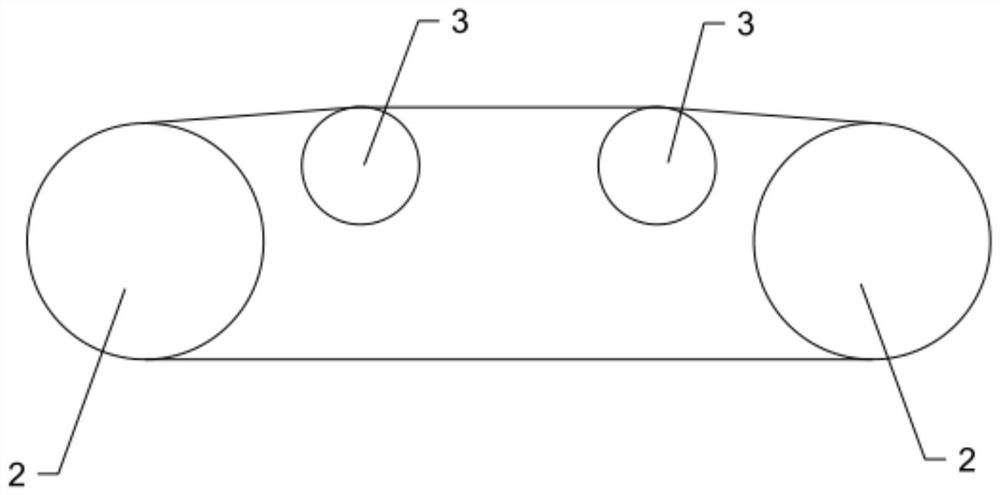
Figure 3
Abstract
Description
technical field
[0001] The invention relates to the technical field of cutting machine manufacturing, in particular to an auxiliary mechanism for adjusting the length of a wire bow. Background technique
[0002] The basic principle of the multi-wire cutting machine is to repeatedly move the cutting wire at high speed. The basic core structure of the multi-wire cutting machine is that the two self-rotating main rollers drive the cutting wire to move. The grinding method is: the workpiece slowly approaches the cutting line, and the high-speed cutting The wire carries the cutting particles to grind the workpiece.
[0003] The two-roller main shaft of the multi-wire cutting machine in the current market generally adopts a fixed wheelbase, and the axial distance between the two main rollers determines the maximum cutting size of the machine. If a small-sized product is cut with a large wheelbase, it will cause an excessively large wire bow, resulting in increased cutting wire lo...
Examples
Embodiment Construction
[0020] In order to make the object, technical solution and advantages of the present invention more clear, the present invention will be further described in detail below in conjunction with the accompanying drawings and embodiments. It should be understood that the specific embodiments described here are only used to explain the present invention, not to limit the present invention.
[0021] Refer to attached Figure 1-5 , the present embodiment includes a frame 1, two main rollers 2 are arranged on the frame 1, two auxiliary rollers 3 are arranged between the two main rollers 2, and eccentric mounting seats 4 are set at both ends of the auxiliary rollers 3, The eccentric mount 4 is installed on the frame 1 through the threaded connector 5, and there are multiple threaded connectors 5, which are distributed in an array around the axis of the eccentric mount 4, and the auxiliary roller 3 is tangent to the cutting line by rotating the eccentric mount 4 Surrounding with each ot...