
USB Type C connector
A connector and the same technology, applied in the direction of connecting parts protective grounding/shielding device, fixed/insulating contact member, etc., can solve the problems of inconvenient soldering of solder feet and PCB board, signal interference, unfavorable high-frequency characteristics of products, etc. Conducive to high frequency characteristics, reduce signal interference, and facilitate welding
Patent Information
- Authority / Receiving Office
- CN · China
- Patent Type
- Applications(China)
- Current Assignee / Owner
- Publication Date
- 2020-12-04
Smart Images
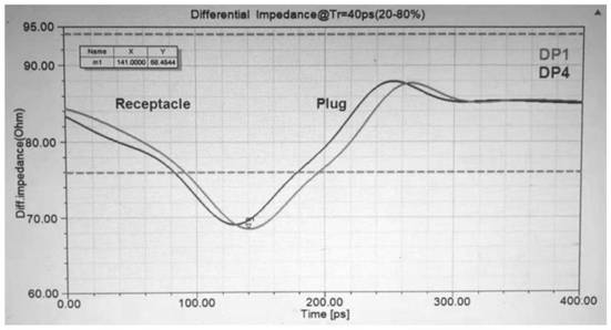
Figure 1 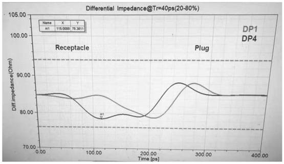
Figure 2 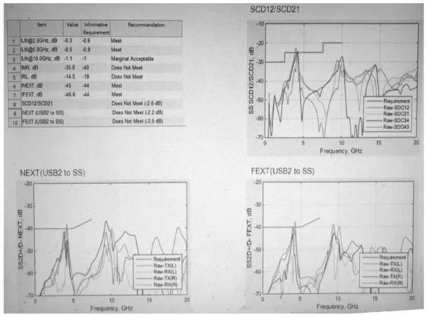
Figure 3
Abstract
Description
technical field
[0001] The invention relates to the technical field of electrical connectors for transmitting data signals, in particular to a USB Type C connector. Background technique
[0002] The distance between adjacent welding legs of conductive terminals on the existing USB Type C connector is relatively narrow, generally 0.5mm, and the row spacing between two adjacent rows of welding legs is also narrow, generally 0.75mm, which is not convenient for soldering. The welding between the feet and the PCB board, and when transmitting signals, signal interference is prone to occur between adjacent welding feet used to transmit high-frequency signals, which is not conducive to the high-frequency characteristics of the product (such as Differential Impedance, ILfitatNq, IMR, IRL, Crosstalk, etc.). Contents of the invention
[0003] The object of the present invention is to at least solve one of the technical problems in the prior art, and provide a USB Type-C connector, w...
Examples
Embodiment Construction
[0022] This part will describe the specific embodiment of the present invention in detail, and the preferred embodiment of the present invention is shown in the accompanying drawings. Each technical feature and overall technical solution of the invention, but it should not be understood as a limitation on the protection scope of the present invention.
[0023] In the description of the present invention, it should be understood that the orientation descriptions, such as up, down, front, back, left, right, etc. indicated orientations or positional relationships are based on the orientations or positional relationships shown in the drawings, and are only In order to facilitate the description of the present invention and simplify the description, it does not indicate or imply that the device or element referred to must have a specific orientation, be constructed and operated in a specific orientation, and thus should not be construed as limiting the present invention.
[0024] I...