
Bidirectional balance double-acting buffer device for hydraulic cylinder piston
A buffer device and double-acting technology, applied in the hydraulic field, can solve the problems of increasing the weight of the oil cylinder, increasing the number of parts, and the complex structure of the buffer technology, so as to ensure reliability and stability, easy processing and assembly, and ease the cumbersome assembly.
Patent Information
- Authority / Receiving Office
- CN · China
- Patent Type
- Applications(China)
- Current Assignee / Owner
- Publication Date
- 2020-12-22
- Estimated Expiration
- Not applicable · inactive patent
Smart Images
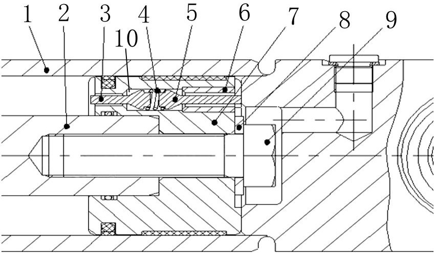
Figure 1
Abstract
Description
Technical field
[0001] The invention belongs to the technical field of hydraulics, and particularly relates to a two-way balanced double-acting buffer device for a hydraulic cylinder piston.Background technique
[0002] The conventional limit displacement buffer structure of the oil cylinder is a combination of adding a buffer sleeve and adding a buffer groove on the guide sleeve and adding a plunger at the end of the piston rod. This structure relies on the guide sleeve groove and the guide sleeve when the limit displacement is about to be reached. When the buffer sleeve is combined, high pressure is generated in its rod cavity to increase the working resistance and reduce the displacement speed of the piston rod, thereby achieving the purpose of buffering; but the high pressure generated at the moment has a higher impact on the wall thickness of the cylinder. It is rarely used on oil cylinders with low telescopic frequency. When resetting, the buffer plunger enters the oil port first, a...
Examples
Embodiment Construction
[0014]The present invention will be further described below based on the drawings and embodiments.
[0015]Such asfigure 1As shown, a hydraulic cylinder piston two-way balanced double-acting buffer device, a piston 7 is placed in the cylinder tube 1 of the hydraulic cylinder, and the piston rod 2 is fixed to the piston 7 through a bolt 9 and a washer 8. The piston 7 is provided with a through valve groove 10 along the axial direction, and the valve groove 10 is used to communicate the large cavity and the small cavity of the hydraulic cylinder. A valve core I3 and a valve core II5 are arranged in the valve groove 10, and both the valve core I3 and the valve core II5 include an oil blocking part (the oil blocking part is used to control the oil passage of the valve groove 10 to connect the large cavity and the small cavity of the hydraulic cylinder The oil blocking part of spool Ⅰ3 and the oil blocking part of spool Ⅱ5 are both located inside the valve groove 10, and the oil blocking pa...