
Computer heat dissipation structure
A heat dissipation structure and computer technology, applied in the computer field, can solve the problems of increasing the difficulty of the computer case, occupying the space of the computer case, increasing the cost of the computer case, etc., and achieving the effects of low probability of failure, less quantity and low cost.
Patent Information
- Authority / Receiving Office
- CN · China
- Current Assignee / Owner
- Publication Date
- 2020-12-25
Smart Images
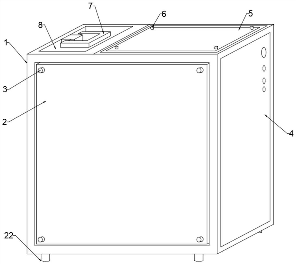
Figure 1 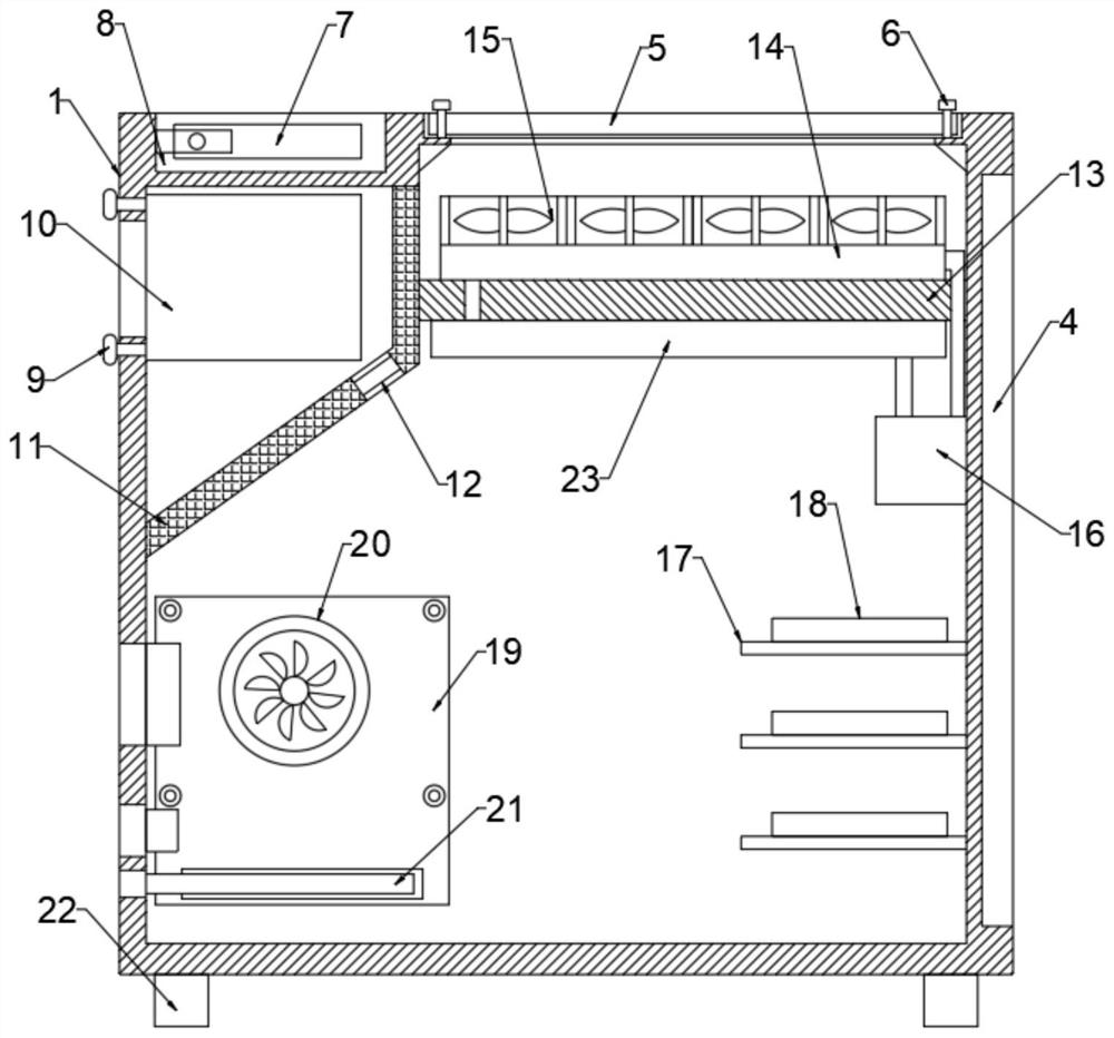
Figure 2
Abstract
Description
technical field
[0001] The invention relates to the technical field of computers, in particular to a computer cooling structure. Background technique
[0002] Desktop computer is commonly called as desktop at present, and desktop chassis is generally the cuboid of side opening. All physical components in the chassis are generally called computer hardware, including hard disks, CPUs, memory sticks, graphics cards, light sources, fans, etc. The motherboard is the installation carrier of the above-mentioned electronic components, and other components are also connected to the motherboard through wires. The CPU and the graphics card are the two heat-generating devices with the largest heat generation in the desktop, so a special fan will be installed in the desktop to cool the CPU and the graphics card.
[0003] In the existing air-cooled desktop computers, in order to enhance the heat dissipation inside the chassis, multiple cooling fans are arranged on both sides of the chas...
Examples
Embodiment Construction
[0034]The following will clearly and completely describe the technical solutions in the embodiments of the present invention with reference to the accompanying drawings in the embodiments of the present invention. Obviously, the described embodiments are only some, not all, embodiments of the present invention.
[0035] In describing the present invention, it should be understood that the terms "upper", "lower", "front", "rear", "left", "right", "top", "bottom", "inner", " The orientation or positional relationship indicated by "outside", etc. is based on the orientation or positional relationship shown in the drawings, and is only for the convenience of describing the present invention and simplifying the description, rather than indicating or implying that the referred device or element must have a specific orientation, so as to Specific orientation configurations and operations, therefore, are not to be construed as limitations on the invention.
[0036] refer to Figure 1...