
Automatic roll changing cutter structure of coating machine
A coating machine and cutting knife technology, applied in the field of coating machines, can solve the problems of reducing customer operability and convenience, and achieve the effect of simple and ingenious structure, less mechanical parts and simple structure
Patent Information
- Authority / Receiving Office
- CN · China
- Patent Type
- Applications(China)
- Current Assignee / Owner
- Publication Date
- 2021-02-26
Smart Images
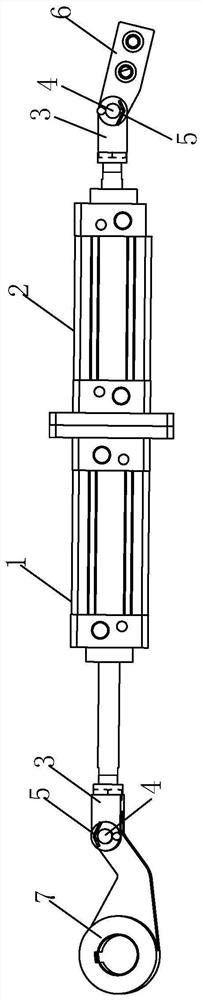
Figure 1 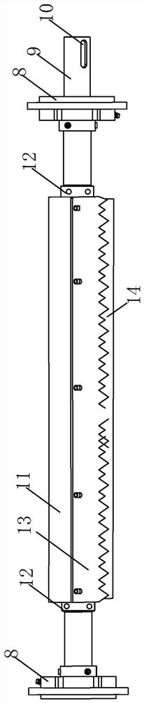
Figure 2 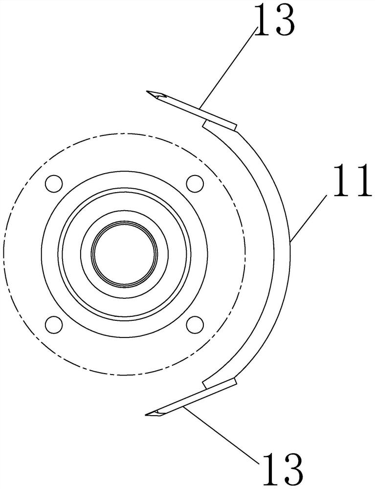
Figure 3
Abstract
Description
technical field
[0001] The invention relates to the technical field of coating machines, in particular to a cutting knife structure for automatic roll changing of coating machines. Background technique
[0002] There are relatively mature unwinding and automatic rewinding and cutting devices in the coating industry, but most of them perform material reloading and cutting on the unwinding of the material roll in one direction (commonly known as upper unwinding or lower unwinding), so the automatic reeling cutter is generally They are all designed to be cut for unwinding in one direction, which reduces the operability and convenience for customers when using. Contents of the invention
[0003] In view of the deficiencies in the prior art, the purpose of the present invention is to provide a cutting knife structure for automatic roll change of a coating machine, which has the effect of strong operability and high convenience.
[0004] Above-mentioned purpose of the invention...
Examples
Embodiment
[0039] refer to Figure 1-6 , which is a cutting knife structure for an automatic roll change of a coating machine disclosed in the present invention, including a knife pushing mechanism and an idle roller cutting knife mechanism.
[0040] The idle roller cutting mechanism includes an idle roller and a semicircular knife mounting frame 11 arranged around the idle roller. The idle roller includes a shaft 9 and a bearing roller 14 arranged on the shaft 9. One end of the shaft 9 is connected with the cutting knife pushing mechanism , and driven by the knife pushing mechanism to rotate.
[0041] Both ends of the shaft rod 9 are provided with a flange bearing seat 8, and the shaft rod 9 is rotationally connected with the flange bearing seat 8, which facilitates the installation of the idler roller, forms a support for the idler roller, and facilitates the rotation of the idler roller.
[0042] The semicircular knife mounting frame 11 is arranged in the shape of a semi-cylindrical ...