
Mechanical collision test device
A test device, a technology of mechanical collision, applied in the direction of measurement device, machine/structural component test, impact test, etc., can solve problems such as failure to meet customer test requirements
Patent Information
- Authority / Receiving Office
- CN · China
- Current Assignee / Owner
- Publication Date
- 2021-03-16
Smart Images
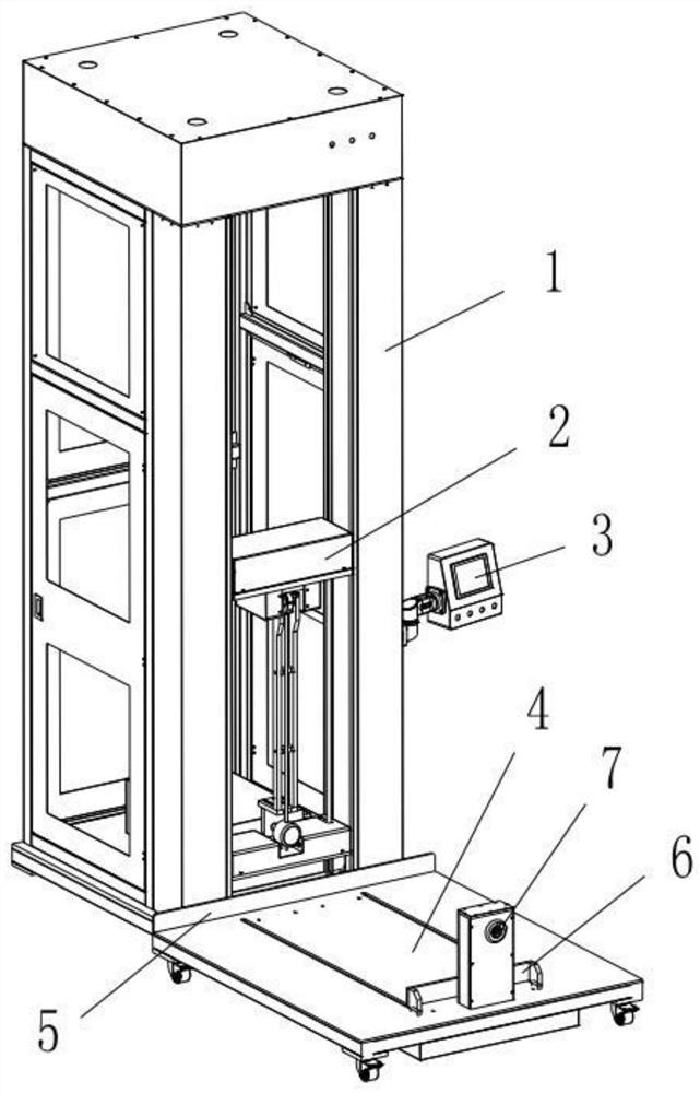
Figure 1 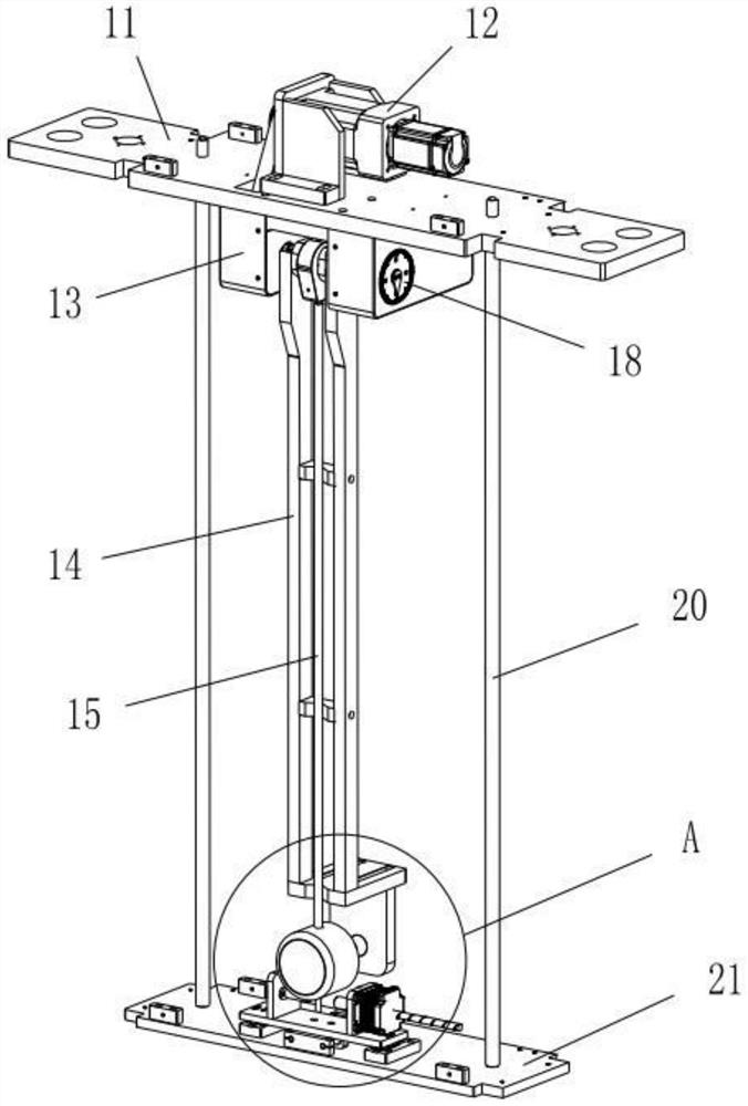
Figure 2 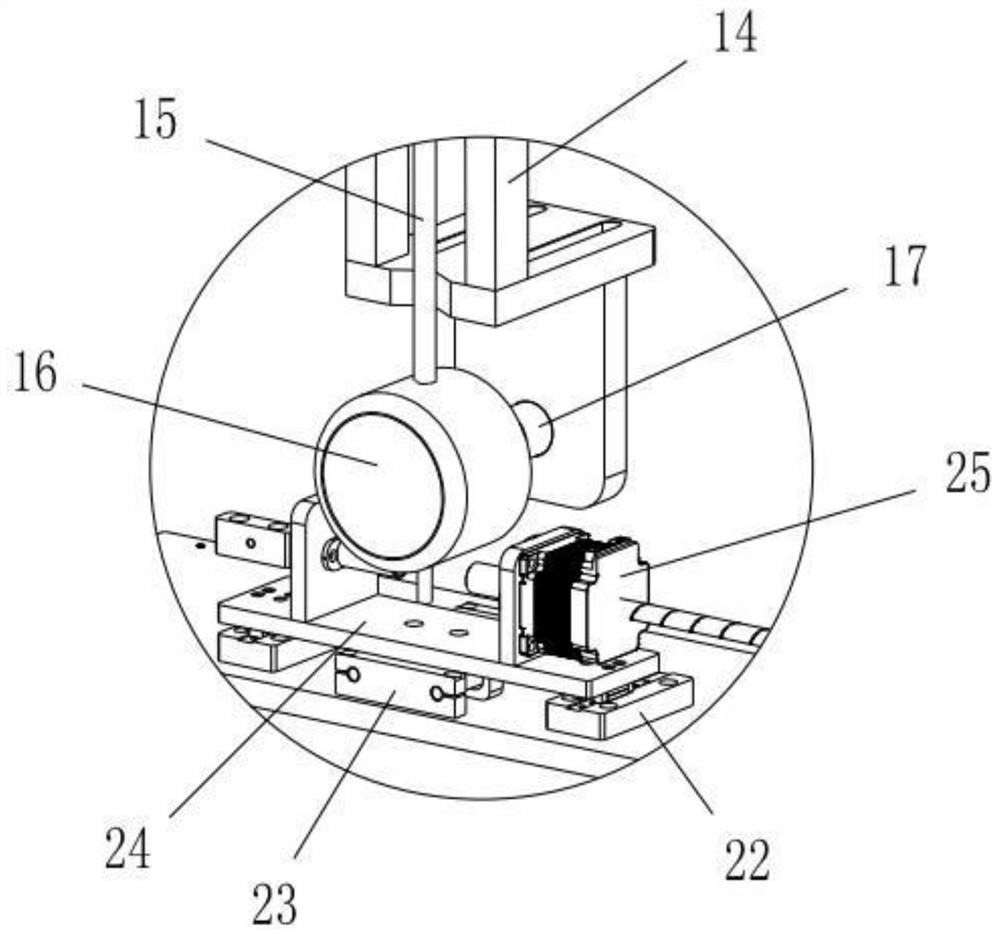
Figure 3
Abstract
Description
technical field
[0001] The invention relates to a mechanical impact test device, which belongs to the technical field of mechanical test equipment. Background technique
[0002] Box-type substations, high-voltage switchgears, JP cabinets, low-voltage switchgears, cable branch boxes, meter boxes and other products need to undergo mechanical collision tests to verify the protection level of the products and whether the mechanical stress of the shell meets the standard. The existing test equipment It is relatively simple and cannot meet the customer's requirements for the test. Contents of the invention
[0003] In view of the above-mentioned existing technical problems, the object of the present invention is to propose a mechanical impact test device.
[0004] The technical solution of the present invention is achieved as follows: a mechanical impact test device, including a frame, a pendulum mechanism and a feeding mechanism; the frame is provided with a lifting drive mech...
Examples
Embodiment Construction
[0016] The present invention is described below in conjunction with accompanying drawing.
[0017] as attached Figure 1-3 As shown, a kind of mechanical impact test device described in the present invention comprises a frame 1, a pendulum mechanism 2 and a discharge mechanism; the frame 1 is provided with a control panel 3 for operation, and the frame 1 is also provided with There is a lifting drive mechanism, which can adopt a conventional motor screw mechanism, and the lifting drive mechanism drives the pendulum mechanism 2 to lift; the discharge mechanism includes a discharge platform 4, and a fixed baffle is arranged on the discharge platform 4 5. The movable baffle 6 and the baffle driving device 7, the baffle driving device 7 drives the movable baffle 6 to move, and the movable baffle 6 and the fixed baffle 5 cooperate to fix the workpiece on the discharging platform 4; the discharging The four corners of the bottom of the carrier 4 are provided with rollers, so that t...