
Joint recovery rehabilitation vehicle
A technology for rehabilitation vehicles and joints, which is applied in the direction of training equipment for adjusting coordination, training equipment for adjusting cardiovascular system, gymnastics equipment, etc. It can solve the problems of not having too much exercise burden for hand and foot movements, muscle and joint injuries, etc. Achieve the effect of preventing joint damage, reducing burden, and improving rehabilitation training
Patent Information
- Authority / Receiving Office
- CN · China
- Current Assignee / Owner
- Publication Date
- 2021-04-06
- Estimated Expiration
- Not applicable · inactive patent
Smart Images
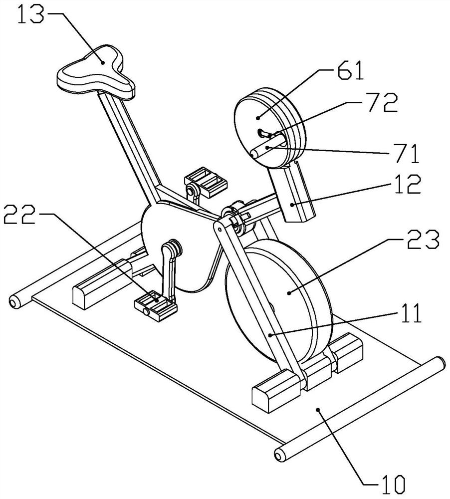
Figure 1 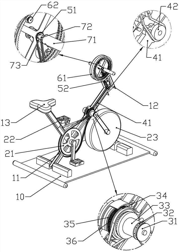
Figure 2 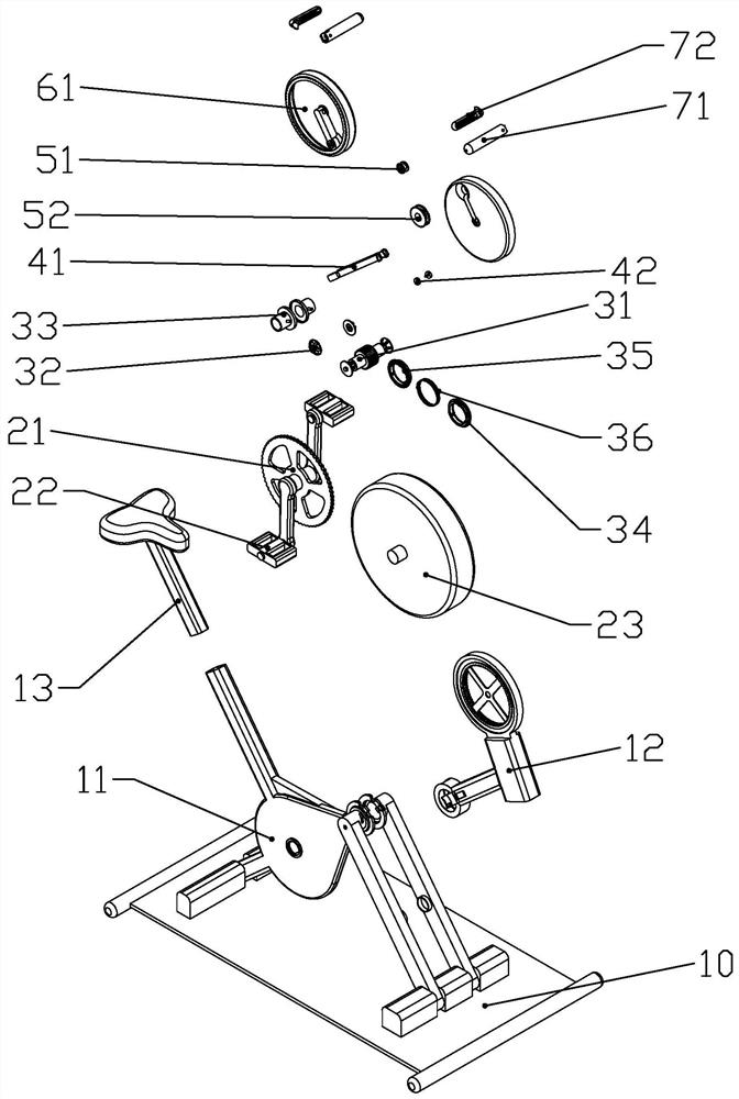
Figure 3
Abstract
Description
technical field
[0001] The invention belongs to the technical field of rehabilitation physiotherapy equipment, and in particular relates to a rehabilitation car for joint recovery. Background technique
[0002] The Chinese patent document whose document number is CN201799060U discloses a kind of exercise bike, which includes a car body, a foot power mechanism and a flywheel. The exercise bike also includes a manual power mechanism and a central transmission mechanism. The center drive drives the flywheel. The exercise bike mentioned above adopts the design of manual power mechanism, foot power mechanism and central transmission mechanism, and the manual power mechanism and foot power mechanism respectively drive the flywheel through the central transmission, thereby realizing independent driving methods for hands and feet, so that hands or feet The feet can get better movement.
[0003] When the above patent is in use, although the independent driving mode of the hands and...
Examples
Embodiment Construction
[0046] according to Figure 1 to Figure 19 As shown, a joint rehabilitation vehicle described in this embodiment includes a vehicle frame 11 and a weight wheel 23 rotatably connected in the vehicle frame 11; the front part of the vehicle frame 11 is rotatably connected with a rotating shaft A main shaft 31 capable of transmission connection with the counterweight wheel 23 is provided along the left and right direction; the main shaft 31 is transmission connected with the counterweight wheel 23 through a counterweight synchronous belt; The front part is rotatably connected with a handwheel frame 12.
[0047] The lower end of the vehicle frame 11 is fixedly connected with a base 10 for supporting the vehicle frame 11; the vehicle frame 11 is provided with a vehicle seat 13 for the user to sit on; the front part of the vehicle frame 11 is formed with two symmetrically arranged The installation pipe seat 111 that is rotatably connected with the main shaft 31; the rear part of the...