
Spherical tooth track running structure and tracked micro-electric vehicle
A driving structure and spherical tooth technology, applied in the field of transmission, can solve the problems of slow running, lack of drag force, and affecting tourists' sightseeing experience, etc., and achieve the effect of reducing manufacturing cost and making it easy to manufacture.
Patent Information
- Authority / Receiving Office
- CN · China
- Current Assignee / Owner
- Publication Date
- 2021-08-03
Smart Images
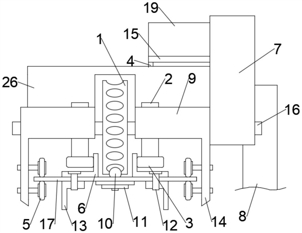
Figure 1 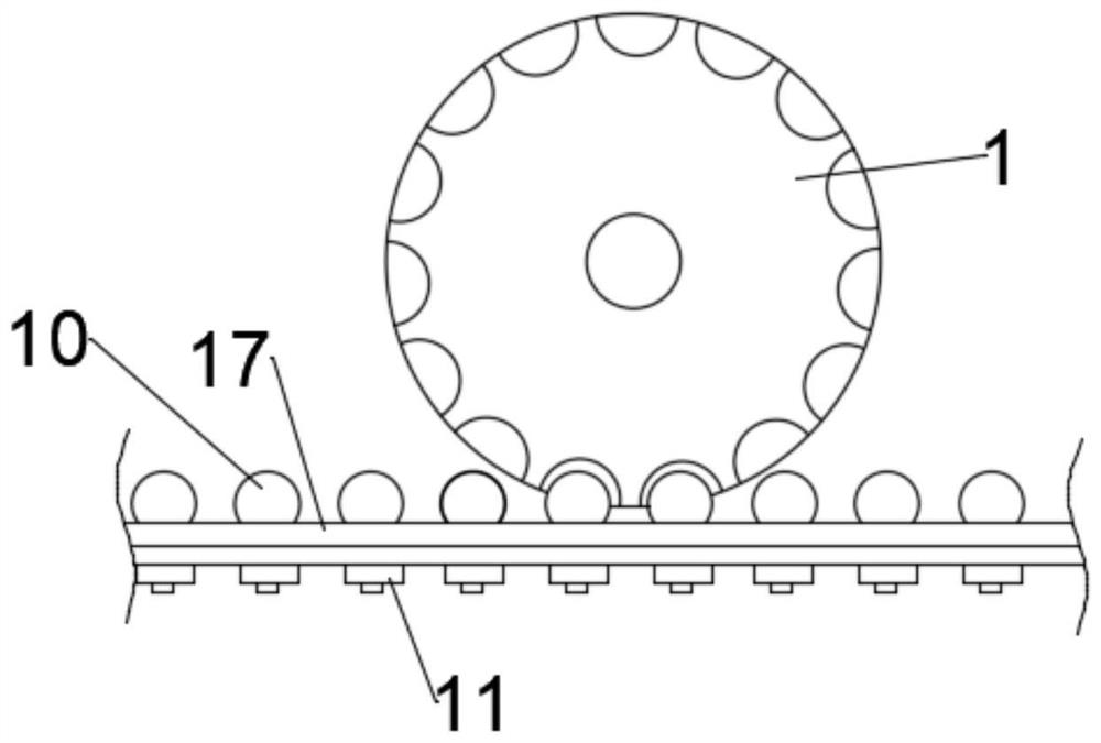
Figure 2 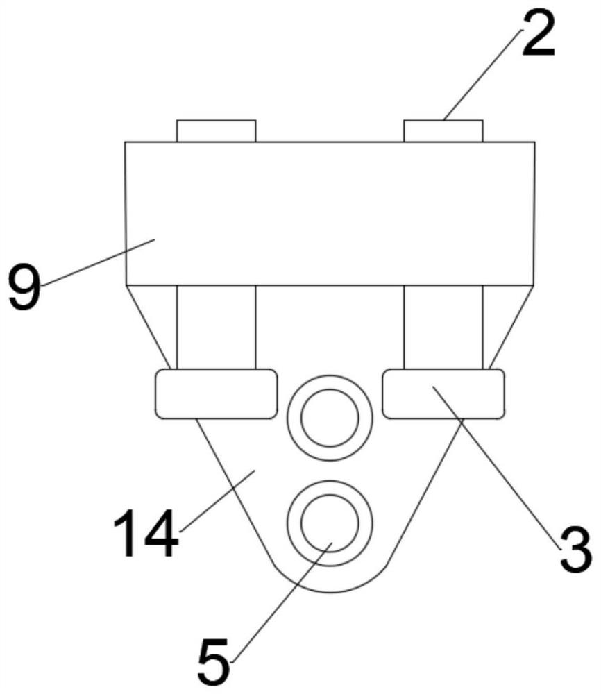
Figure 3
Abstract
Description
technical field
[0001] The invention belongs to the technical field of transmission, and in particular relates to a spherical tooth track driving structure and a rail micro-tram. Background technique
[0002] At present, the tramway is mainly used for driving along the terrain in the scenic spot, and for sightseeing and travel. Due to the complex terrain of the scenic spot, it often needs to go uphill or downhill continuously, and at the same time, it needs to carry people on steep slopes.
[0003] The current trams cannot continue climbing or descending steep slopes, and when encountering steep slopes, they often suffer from lack of drag force, which makes the trams travel very slowly and affects the sightseeing experience of tourists. Contents of the invention
[0004] In order to solve the above-mentioned technical problems, the present invention provides a spherical gear track driving structure and a tramway, which can adapt to most complex terrains through the drive o...
Examples
Embodiment
[0040] like Figure 1-5 As shown, the present embodiment provides a spherical tooth track driving structure, including: a track 17, a concave tooth drive gear 1, a guide assembly and a locking rail assembly.
[0041] The rail 17 is provided with a guide rail 6 arranged along the length direction of the rail 17 and a plurality of spherical teeth 10 arranged at equal intervals. The concave tooth drive gear 1 is provided with concave teeth adapted to the spherical teeth 10 . The concave-tooth drive gear 1 is rotatably connected to the guide assembly, and one end of the guide assembly is connected to the guide rail 6. Through the cooperation between the guide assembly and the guide rail 6, the concave-tooth drive gear 1 is kept rotating along the laying direction of the spherical teeth 10. The concave-tooth drive gear 1 When rotating, the spherical tooth 10 meshes with the concave tooth. One end of the lock rail assembly is connected with the guide assembly, and the other end is...