
Array displacement measuring device and method for slope slippage and settlement monitoring
A technology for settlement monitoring and displacement measurement, applied in the direction of measuring devices, electric devices, and electromagnetic means, can solve the problems of limited and cumbersome measurement angles, repeated layout of inclinometers and settlement meters, etc., and achieve simple layout and use Convenient and realize the effect of automatic measurement
Patent Information
- Authority / Receiving Office
- CN · China
- Patent Type
- Applications(China)
- Current Assignee / Owner
- Publication Date
- 2022-01-21
Smart Images

Figure 1 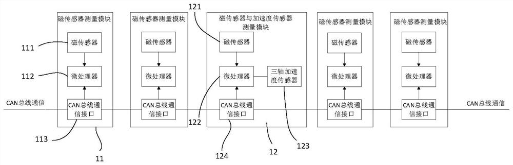
Figure 2 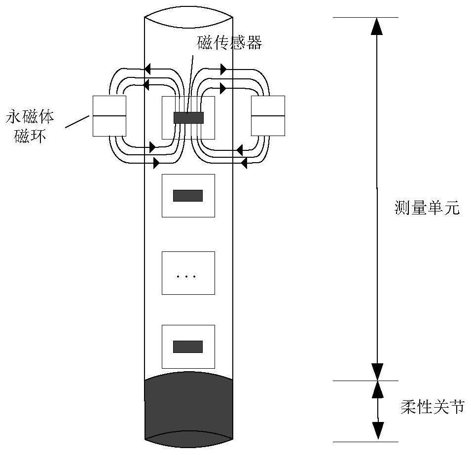
Figure 3
Abstract
Description
technical field
[0001] The invention relates to the technical field of deformation monitoring, in particular to an array displacement measuring device and method for slope slip and settlement monitoring. Background technique
[0002] The conventional array displacement gauge is a sensor for measuring acceleration and displacement based on the testing principle of micro-electromechanical systems. It connects adjacent steel pipes through flexible joints, and the sensors are placed in the steel pipes. It can be used for deformation testing of geotechnical engineering under static conditions.
[0003] When used for deformation monitoring such as slope slippage, it needs to be placed in the inclinometer tube. Since the array displacement gauge has no support structure, it is easy to slide freely in the inclinometer tube, so the displacement of the ordinary array displacement gauge cannot reflect the real situation. Slope slippage; in addition, at present, inclinometers and settle...
Examples
Embodiment Construction
[0026] In order to make the purpose, technical solutions and advantages of the embodiments of the present invention clearer, the technical solutions in the embodiments of the present invention will be clearly and completely described below in conjunction with the drawings in the embodiments of the present invention. Obviously, the described embodiments It is a part of embodiments of the present invention, but not all embodiments. Based on the embodiments of the present invention, all other embodiments obtained by persons of ordinary skill in the art without making creative efforts belong to the protection scope of the present invention.
[0027] see figure 1 , is a structural view of one embodiment of the array displacement measurement device used for slope slip and settlement monitoring in the present invention, the device includes a plurality of steel pipes 1 with pulleys connected in series, and a flexible The joints 2 are connected, and each steel pipe 1 is equipped with ...