
Clean channel system for large component purification
A large component, clean technology, applied in the field of purification, can solve the problems of low automation, poor cleaning effect, inability to clean and dry large components, etc., and achieve the effect of high automation and good ability to clean large components
Patent Information
- Authority / Receiving Office
- CN · China
- Current Assignee / Owner
- Publication Date
- 2022-02-25
Smart Images
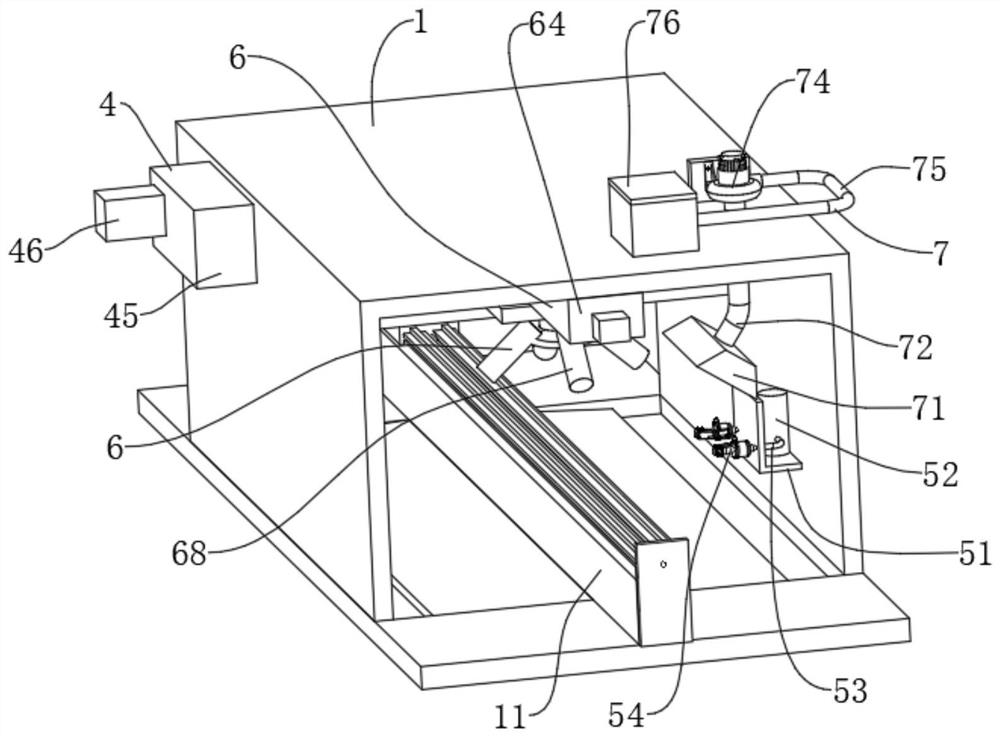
Figure 1 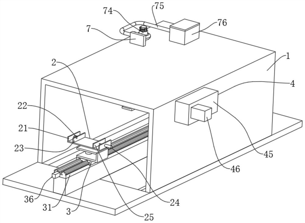
Figure 2 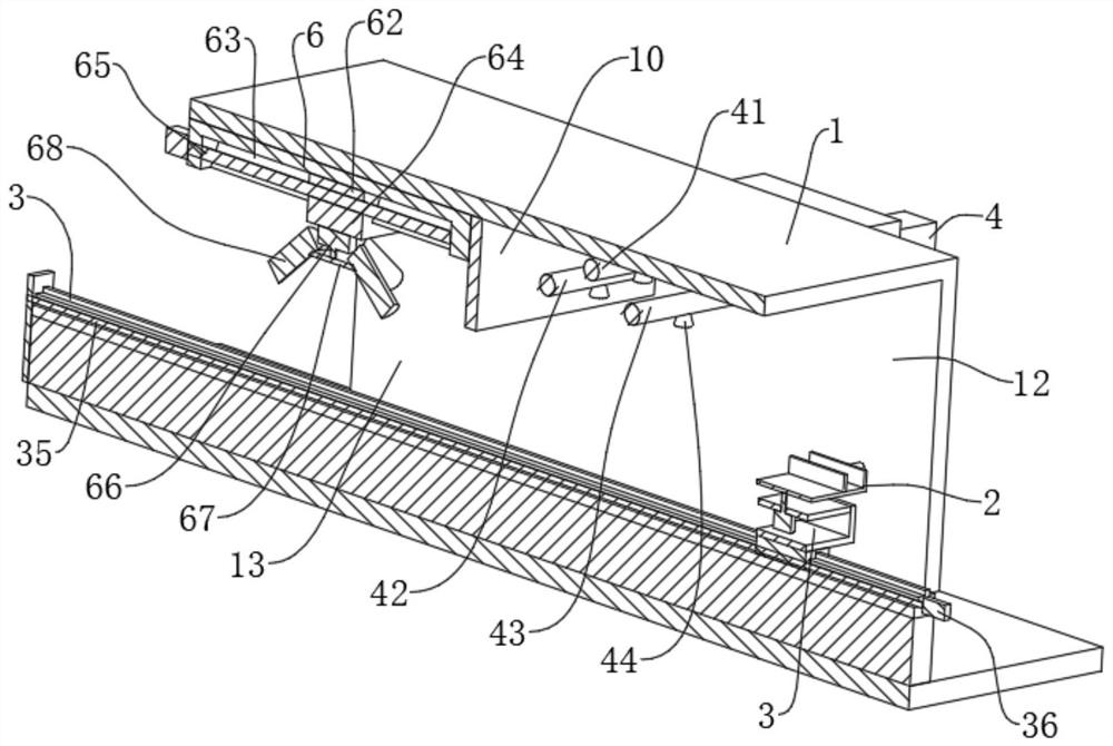
Figure 3
Abstract
Description
technical field
[0001] The invention relates to the field of purification, in particular to a clean passage system for large component purification. Background technique
[0002] With the continuous improvement of clean production environment requirements in various industries, higher requirements are put forward for the cleanliness of production areas. Personnel showers and cargo showers can no longer fully cover all the technical requirements of clean passages, especially Aerospace and large-scale component assembly plants must build super-large cargo shower channels to meet process requirements due to access to super-large components (width or height greater than 4m).
[0003] In order to meet the needs of end customers, it is very necessary to develop a traditional clean room that is different from a box with a sliding door. This is a new challenge for the entire industry, and it is also an opportunity and opportunity for corporate technology improvement. Under the back...
Examples
Embodiment 1
[0044] refer to figure 1 , figure 2 and image 3 , a clean channel system for purification of large components, a clean channel system for purification of large components, comprising a clean room 1, further comprising: a hermetic door arranged at openings on both sides of said clean room 1; arranged in said clean room 1 The fixed seat 11; the fixed assembly 2 used to fix large components; the power assembly 3 used to drive the fixed assembly 2 for horizontal transmission and rotation change; the partition plate 10 fixed on the top of the clean room 1, the The partition plate 10 divides the clean room 1 into a first chamber 12 and a second chamber 13; the spray assembly 4 arranged in the first chamber 12 for spray cleaning; The blowing assembly 5 in the second chamber 13; the air-heating assembly 6 arranged on the side wall of the second chamber 13; and the ventilation and ventilation assembly 7 for ventilation.
[0045] refer to figure 1 , figure 2 and image 3 , this...