
Optical lens and electronic equipment
An optical lens and lens technology, applied in optics, optical components, instruments, etc., can solve the problems that affect the miniaturization characteristics of the lens and increase the production cost of the lens, and achieve the effect of low cost and large central angular resolution
Patent Information
- Authority / Receiving Office
- CN · China
- Patent Type
- Applications(China)
- Current Assignee / Owner
- Publication Date
- 2022-03-29
Smart Images
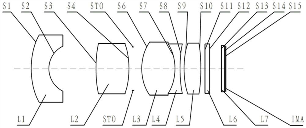
Figure 1 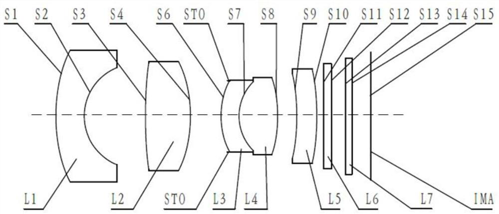
Figure 2 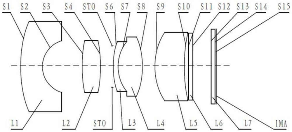
Figure 3
Abstract
Description
technical field
[0001] The present application relates to the field of optical elements, and more specifically, to an optical lens and electronic equipment. Background technique
[0002] In recent years, with the rapid development of automobile auxiliary driving systems, the application of optical lenses in automobiles has become more and more extensive. At the same time, users have higher and higher requirements for the imaging quality of vehicle lenses. In order to meet the application requirements of vehicle-mounted front-view lenses, more and more lens manufacturers have begun to study how to make vehicle-mounted front-view lenses with features such as miniaturization and high pixels.
[0003] At present, in order to improve the resolution capability of the existing vehicle optical lens, most lens manufacturers usually increase the number of lenses to improve the resolution capability of the lens, but this will affect the miniaturization of the lens to a certain extent ...
Examples
Embodiment 1
[0116] Refer to the following figure 1 An optical lens according to Embodiment 1 of the present application is described. figure 1 A schematic structural diagram of the optical lens according to Embodiment 1 of the present application is shown.
[0117] like figure 1 As shown, the optical lens sequentially includes a first lens L1 , a second lens L2 , a third lens L3 , a fourth lens L4 and a fifth lens L5 along the optical axis from the object side to the image side.
[0118] The first lens L1 is a convex-concave lens with negative refractive power, the object side S1 is convex, and the image side S2 is concave. The second lens L2 is a biconvex lens with positive refractive power, the object side S3 is convex, and the image side S4 is convex. The third lens L3 is a biconvex lens with positive refractive power, the object side S6 is convex, and the image side S7 is convex. The fourth lens L4 is a biconcave lens with negative refractive power, the object side S7 is concave, ...
Embodiment 2
[0131] Refer to the following figure 2 An optical lens according to Embodiment 2 of the present application is described. In this embodiment and the following embodiments, for the sake of brevity, descriptions similar to those in Embodiment 1 will be omitted. figure 2 A schematic structural view of the optical lens according to Embodiment 2 of the present application is shown.
[0132] like figure 2 As shown, the optical lens sequentially includes a first lens L1 , a second lens L2 , a third lens L3 , a fourth lens L4 and a fifth lens L5 along the optical axis from the object side to the image side.
[0133] The first lens L1 is a convex-concave lens with negative refractive power, the object side S1 is convex, and the image side S2 is concave. The second lens L2 is a biconvex lens with positive refractive power, the object side S3 is convex, and the image side S4 is convex. The third lens L3 is a convex-concave lens with negative refractive power, the object side S6 is...
Embodiment 3
[0142] Refer to the following image 3 An optical lens according to Embodiment 3 of the present application is described. image 3 A schematic structural diagram of an optical lens according to Embodiment 3 of the present application is shown.
[0143] like image 3 As shown, the optical lens sequentially includes a first lens L1 , a second lens L2 , a third lens L3 , a fourth lens L4 and a fifth lens L5 along the optical axis from the object side to the image side.
[0144] The first lens L1 is a convex-concave lens with negative refractive power, the object side S1 is convex, and the image side S2 is concave. The second lens L2 is a biconvex lens with positive refractive power, the object side S3 is convex, and the image side S4 is convex. The third lens L3 is a convex-concave lens with negative refractive power, the object side S6 is convex, and the image side S7 is concave. The fourth lens L4 is a biconvex lens with positive refractive power, the object side S7 is conv...