
Clinical antenatal diagnosis and examination device based on obstetrics and gynecology department
A prenatal diagnosis and inspection device technology, applied in the field of medical devices, can solve problems such as long inspection time, easy to catch cold, and inability of pregnant women to achieve the effect of maintaining stability, increasing coordination, and avoiding reversal
Patent Information
- Authority / Receiving Office
- CN · China
- Patent Type
- Applications(China)
- Current Assignee / Owner
- Publication Date
- 2022-04-29
- Estimated Expiration
- Not applicable · inactive patent
Smart Images
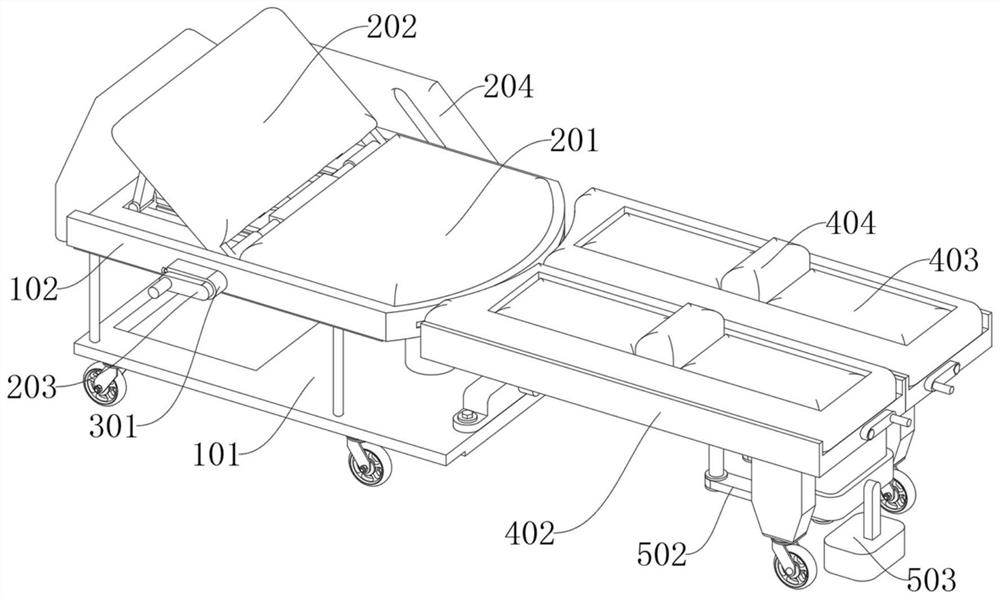
Figure 1 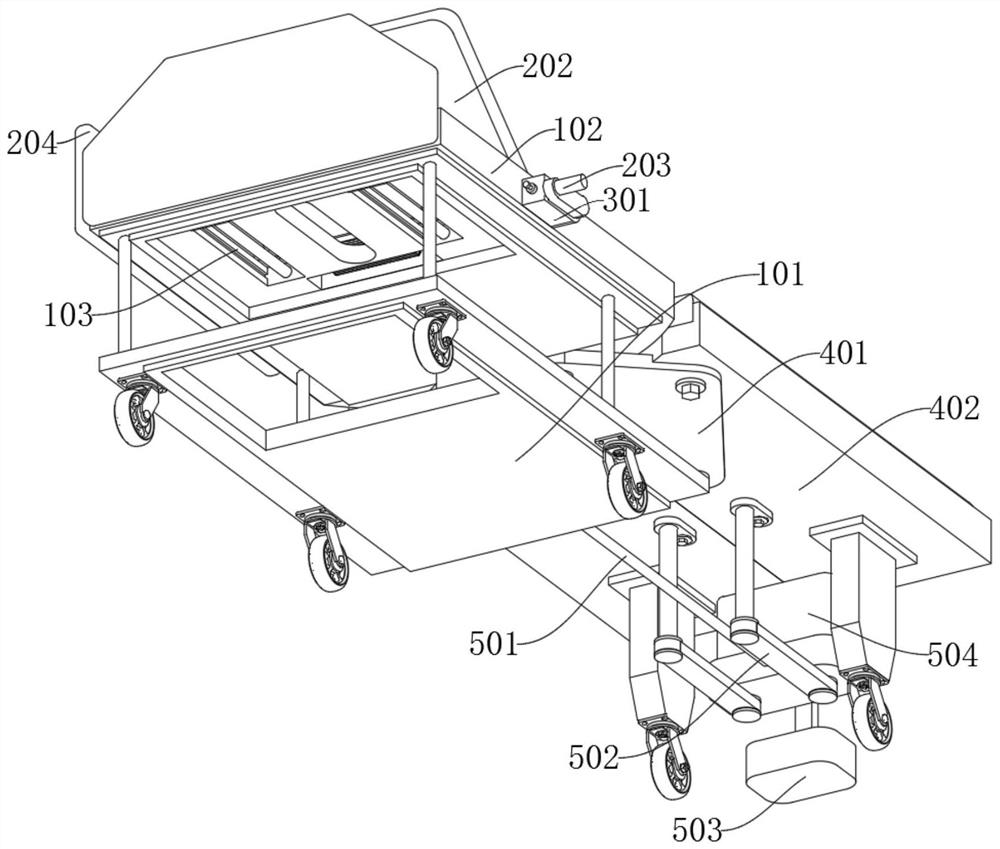
Figure 2 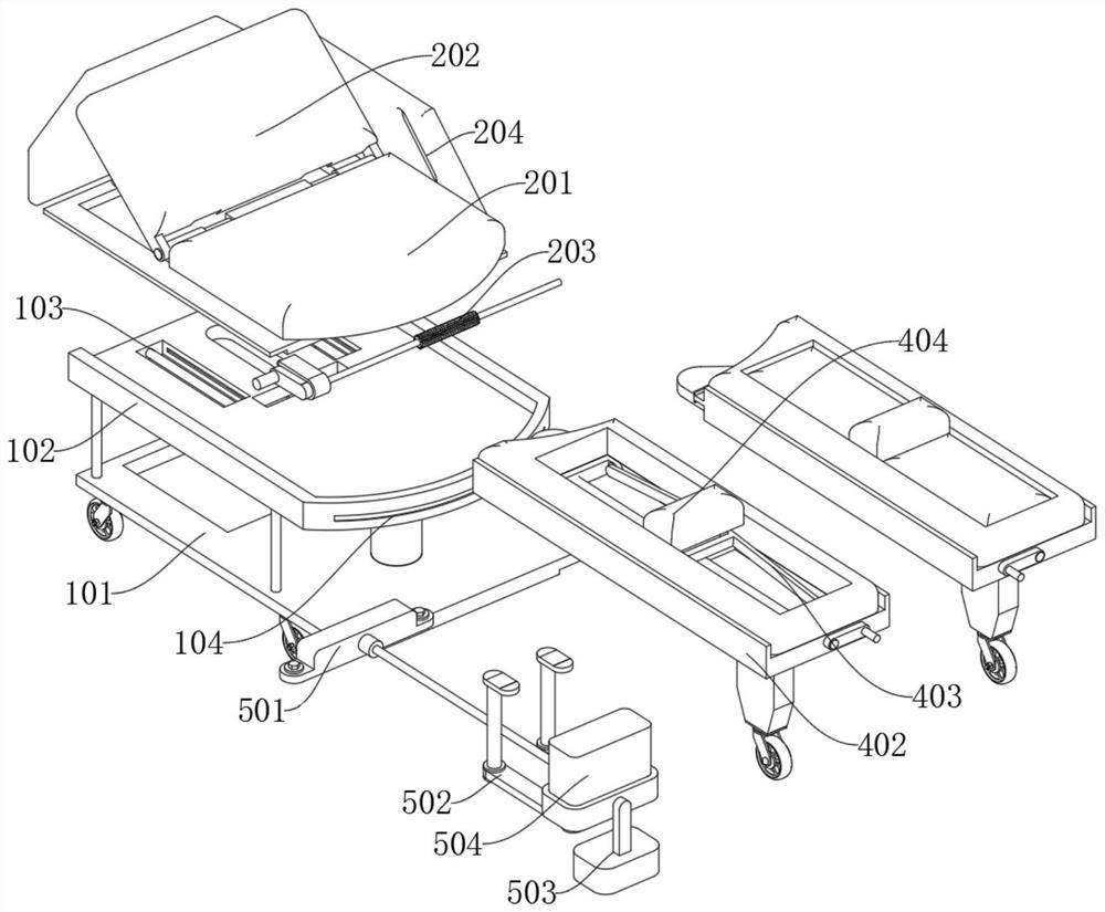
Figure 3
Abstract
Description
technical field
[0001] The invention relates to the technical field of medical devices, in particular to a prenatal diagnosis and inspection device for clinical use in obstetrics and gynecology. Background technique
[0002] Prenatal examination refers to the provision of a series of simple medical and nursing measures and measures for pregnant women, the purpose of which is to prevent and detect complications early and reduce their adverse effects through the monitoring of pregnant women and fetuses. Providing correct examination methods and medical advice during this period is the key to reducing maternal mortality and neonatal mortality. Therefore, a clinical prenatal diagnostic examination device is needed to assist in the examination of pregnant women.
[0003] However, as far as the current traditional gynecological examination devices are concerned, most pregnant women lie directly on the hospital bed and open their legs for examination. During pregnancy, their legs a...
Examples
Embodiment
[0047] Example: Please refer to Figure 1 to Figure 11 :
[0048] The present invention proposes a prenatal diagnosis inspection device based on obstetrics and gynecology clinics, comprising: a support part 1; the support part 1 includes: a top frame 102, the top frame 102 is a square plate structure, and Rectangular groove, the bottom of the left side of the top frame 102 is provided with a cylindrical protrusion; the top frame 102 is used to install the control part 2; the control part 2, the control part 2 is arranged above the support part 1, and the brace 201 Fixedly connected above the top frame 102, the lower end of the flip frame at the bottom of the flip plate 202 of the control part 2 is slidably connected in the sliding groove 103 of the support part 1, and the control rod 203 of the control part 2 is connected to the top frame 102 in rotation, and the control part The side plate 204 of 2 is fixedly connected to the top rear side of the top frame 102; the limiting ...