
Water turbine volute internal corner backfill grouting auxiliary structure and backfill grouting method
A backfill grouting and auxiliary structure technology, which is applied in filling, infrastructure engineering, hydropower generation, etc., can solve the problems of arranging grouting boxes and grouting pipes, poor grouting effect, and long grouting pipes, etc. Easy grouting and low grouting pressure
Patent Information
- Authority / Receiving Office
- CN · China
- Patent Type
- Applications(China)
- Current Assignee / Owner
- Publication Date
- 2022-04-29
Smart Images
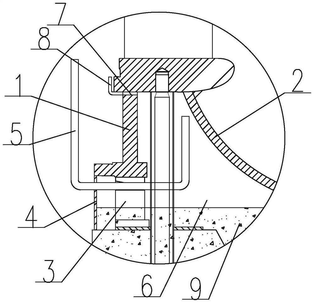
Figure 1 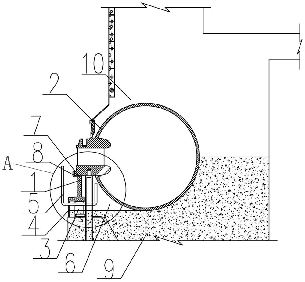
Figure 2
Abstract
Description
technical field
[0001] The invention relates to backfilling and grouting technology for internal corners of hydropower stations and large pumping stations, in particular to the technical field of backfilling and grouting for internal corners of volute casings of hydraulic turbines. Background technique
[0002] The volute and outsourcing concrete of most power stations need to jointly bear the internal water pressure of the volute. The pouring and compactness of the outsourcing concrete is crucial to the safety of the structure. Generally, the requirements for the backfill grouting of the inner corner of the volute and the pressure relief of the volute are: the concrete below the installation elevation needs to be poured for 28 days before the backfill grouting can be performed, and the last warehouse of the entire outsourcing concrete is poured 28 days after the concrete is poured and the volute is 7 days after the backfill grouting is completed. Can release pressure. Acco...
Examples
Embodiment Construction
[0025] The present invention will be further described below in conjunction with the accompanying drawings and specific embodiments.
[0026] Such as figure 1 As shown, an auxiliary structure for backfilling and grouting of the inner corner of the volute of a water turbine according to the present invention is used for backfilling and grouting the inner corner of the volute 6 between the inner side of the volute 2 and the seat ring 1, and is characterized in that it includes a temporary The support seat 3, the inner formwork 4 and the grouting pipe 5, a number of temporary support seats 3 and the inner formwork 4 are arranged around the bottom of the seat ring 1, the inner formwork 4 is vertically arranged on the inner side of the temporary support seat 3, and the grouting pipe 5 extends from the inner side of the seat ring 1 through the gap between the inner template 4 and the adjacent temporary support seat 3 to the inner corner part 6 of the volute.
[0027] The inlet end ...