
Searchlighting range adjusting device for high lighting pole and using method of searchlighting range adjusting device
A technology of adjusting device and range, which is applied in the field of searchlight range adjusting device for lighting high poles, can solve the problems of affecting the light transmittance, pulling the wire, and disconnecting the wire, so as to increase the irradiation range, increase the stability, and improve the The effect of firmness
Patent Information
- Authority / Receiving Office
- CN · China
- Patent Type
- Applications(China)
- Current Assignee / Owner
- Publication Date
- 2022-07-12
Smart Images
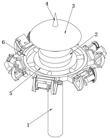
Figure 1 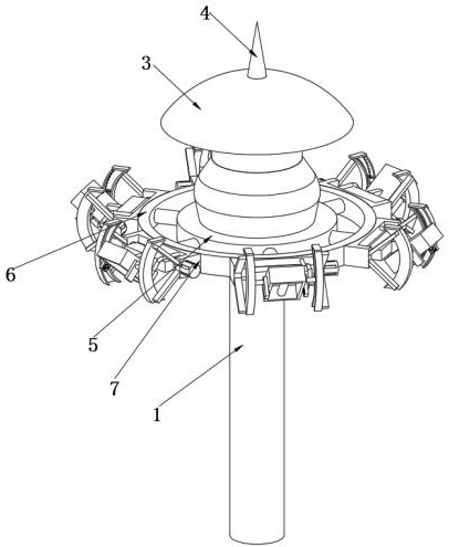
Figure 2 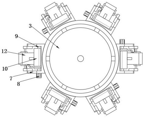
Figure 3
Abstract
Description
technical field
[0001] The invention relates to the technical field of searchlight adjustment equipment for high poles, in particular to a searchlight range adjustment device for lighting high poles and a method for using the same. Background technique
[0002] The searchlight has a powerful light source and a concave mirror that can concentrate the light in a specific direction. It is used for long-distance lighting and search purposes. It can use a reflector or lens to concentrate the emitted beam in a small solid angle to obtain a relatively small solid angle. Large light intensity, most searchlights are attached with high poles or movable vehicles, large searchlights even have special trucks as vehicles, searchlights need to swing the lamp head to achieve the searchlight effect, the existing lighting on construction sites and roads It is generally hung on a rod;
[0003] However, when the existing searchlight equipment is in use, the angle of the searchlight is artifici...
Examples
Embodiment 1
[0037] see Figure 1-9 As shown, the present invention is a detection range adjustment device for a lighting high pole, comprising a support rod 1, the upper surface of the support rod 1 is fixedly connected with a fixing frame 2, and the side of the fixing frame 2 away from the support rod 1 is fixedly connected with a protection Plate 3, the upper surface of the protective plate 3 is fixedly connected with a lightning rod 4, the outer surface of the fixing frame 2 is sleeved with a support frame 5, the outer surface of the support frame 5 is sleeved with a positioning plate 6, and the outer surface of the positioning plate 6 is fixedly connected with a fixing plate 7. One side of the fixed plate 7 is fixedly connected with a servo motor 8, and the inside of the fixed plate 7 is rotatably connected with a drive shaft 9, and one end of the drive shaft 9 is connected with the servo motor 8, and the outside of the drive shaft 9 is sleeved with a positioning sleeve plate 10. The ...
Embodiment 2
[0040] In addition, when the device adjusts the angle of the lighting lamp 12, the servo motor 8 on the fixed plate 7 is made to work, so that the servo motor 8 drives the drive shaft 9 to rotate, and with the rotation of the drive shaft 9, the drive shaft 9 drives the positioning sleeve. 10 synchronously rotates inside the fixed plate 7, and the lighting lamp 12 on the positioning sleeve 10 follows the movement, thereby changing the illumination range of the lighting lamp 12, and driving the spoiler mechanism in the process of changing the angle of the lighting lamp 12 14 to work, so that the spoiler mechanism 14 drives the reinforcement mechanism 15 to follow the work, and the reinforcement mechanism 15 includes a blocking slide 16, and the blocking slide 16 is arranged symmetrically up and down with the center line of the guide rail 141, and the interior of the guide rail 141 is provided with The positioning grooves matched with the shielding slides 16, the two extruding pla...