
Heat sink
A heat dissipation device and fan frame technology, which is applied to pump devices, parts of pumping devices for elastic fluids, non-variable pumps, etc., can solve the problem that the fluid performance of the blower has no substantial effect, and the ribs cannot provide flow guide Problems such as function or anti-backflow effect
Patent Information
- Authority / Receiving Office
- CN · China
- Current Assignee / Owner
- Publication Date
- 2006-01-18
Smart Images
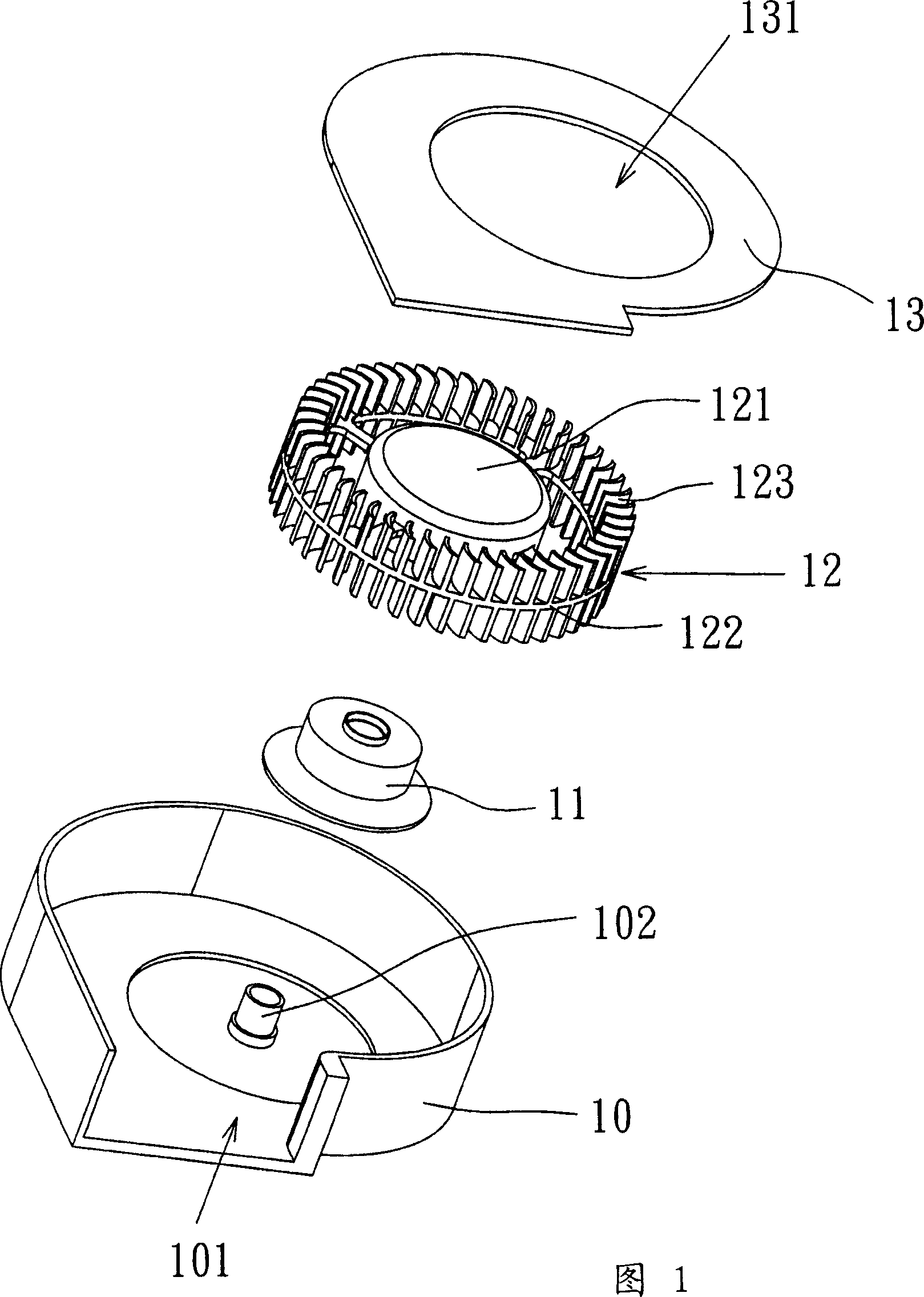
Figure 1 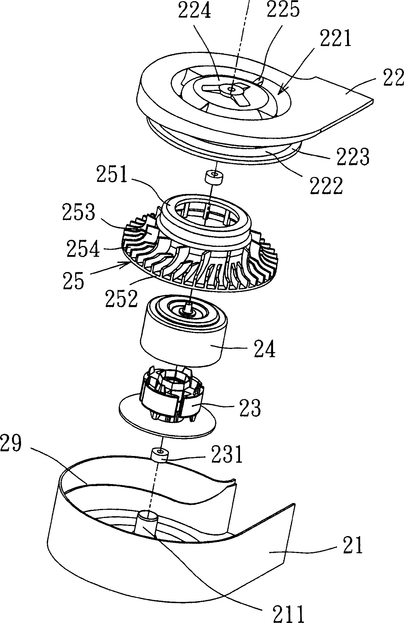
Figure 2 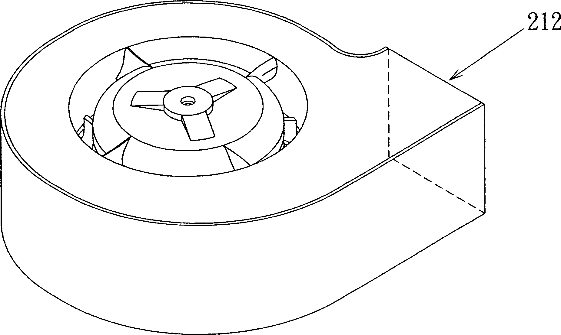
Figure 3
Abstract
Description
technical field
[0001] The invention relates to a cooling device, in particular to a centrifugal fan capable of increasing and stabilizing wind pressure. Background technique
[0002] Generally existing blower, as shown in Figure 1, it comprises an outer frame 10, a motor 11, a blade structure 12 and a loam cake 13, wherein this outer frame 10 has an opening 101, as the air outlet of blower, The motor 11 is set on the base 102 of the outer frame 10 to rotate the blade structure 12 . The upper cover 13 has a circular opening 131 for the air inlet of the blower. The fan blade structure 12 further includes a hub 121 , an annular plate 122 and a plurality of vanes 123 disposed thereon. However, in this traditional blower design, since the blades are in direct contact with the flow channel, and the upper and lower air gaps of the blades are large, it is difficult to control the direction of the airflow, and it is easy to cause air backflow, resulting in low heat dissipation eff...
Examples
Embodiment Construction
[0029] see Figure 2A to Figure 2C , which shows the first preferred embodiment of the heat sink of the present invention. In this embodiment, a centrifugal fan is taken as an example, but the design method can also be applied to an axial fan. The centrifugal fan is a one-way blower, which mainly includes a first frame 21 , a second frame 22 , a driving device 23 , an iron shell 24 and a rotor blade 25 . The first frame 21 has a socket seat 211 on which the driving device 23 can be placed, and a bearing 231 is placed in the socket seat 211 to support the rotating shaft 27 of the rotor blade portion 25 . The second frame 22 has an air inlet 221 and a wall 222 extending downward from the inner edge of the air inlet. When the second frame 22 is combined with the first frame 21, the second frame 22 The space formed after being combined with the first frame 21 is separated to define an air collecting channel 26 and a space for accommodating the rotor blade 25 , and also forms an ...