
Illumination device and image scanning device
A lighting device, rod-shaped technology, applied in the direction of image communication, electrical components, etc., can solve the problems of long length, can not be used as a light source, etc., to achieve the effect of reducing interference
Patent Information
- Authority / Receiving Office
- CN · China
- Current Assignee / Owner
- Publication Date
- 2006-07-12
- Estimated Expiration
- Not applicable · inactive patent
Smart Images
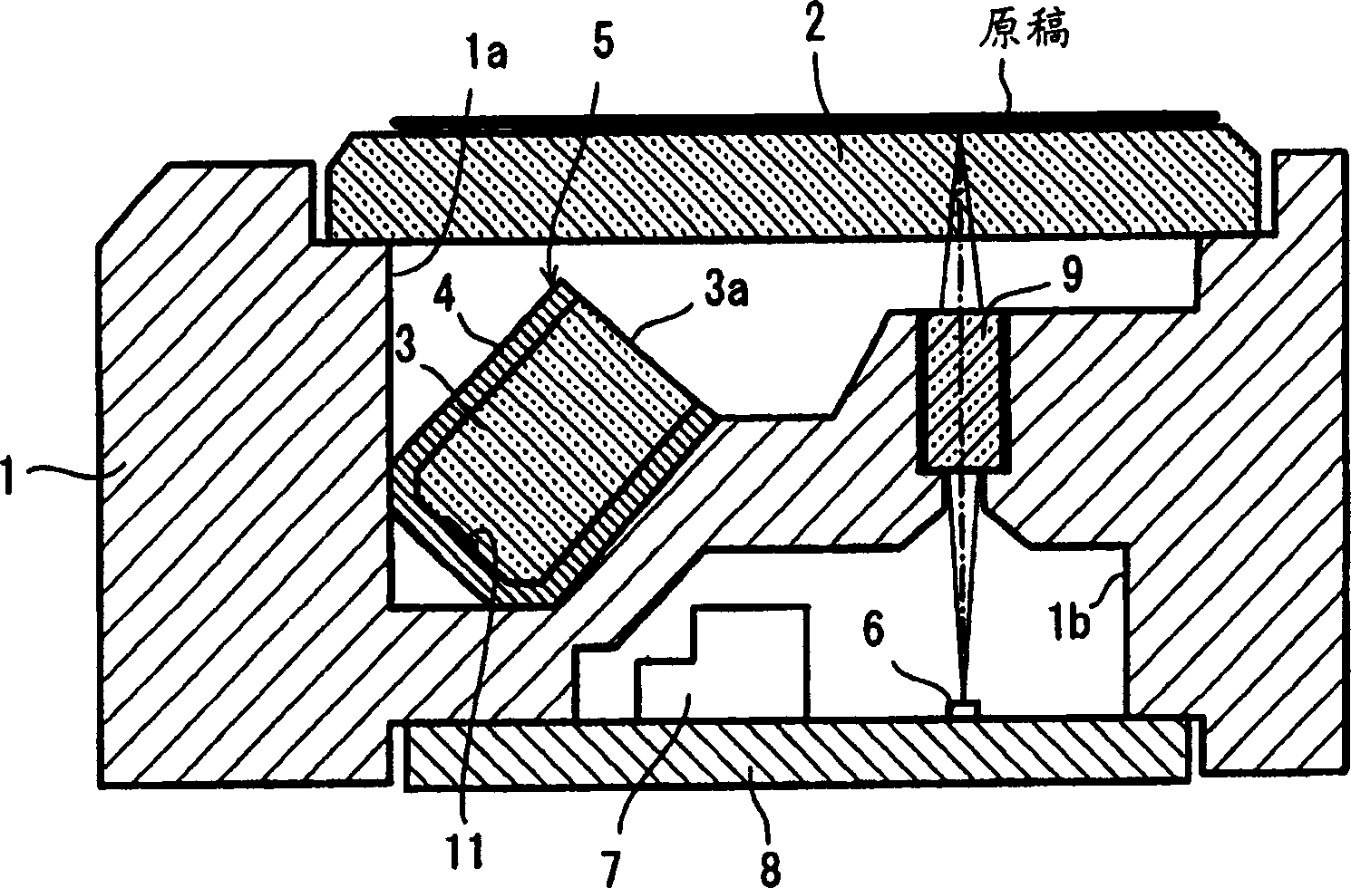
Figure 1 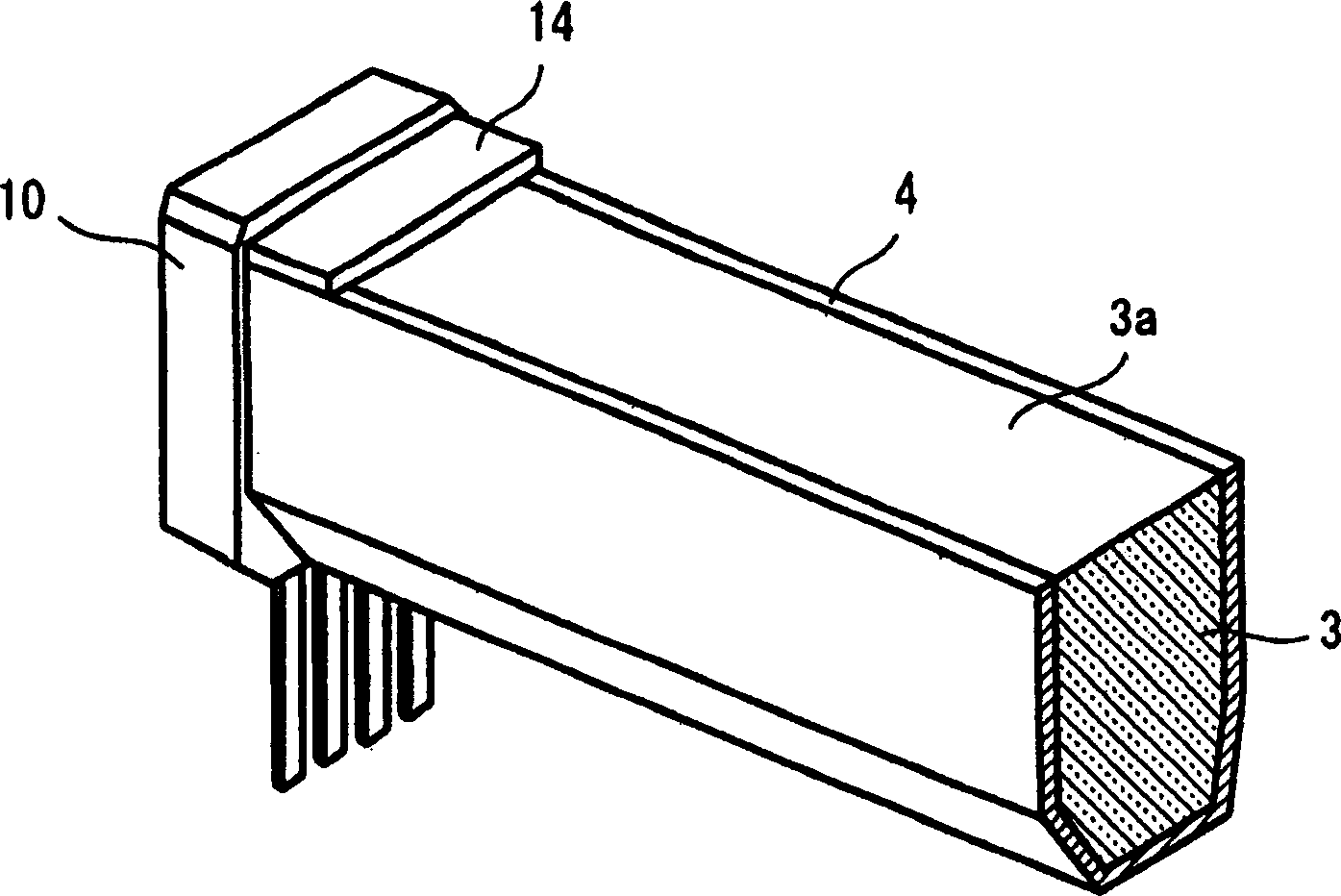
Figure 2 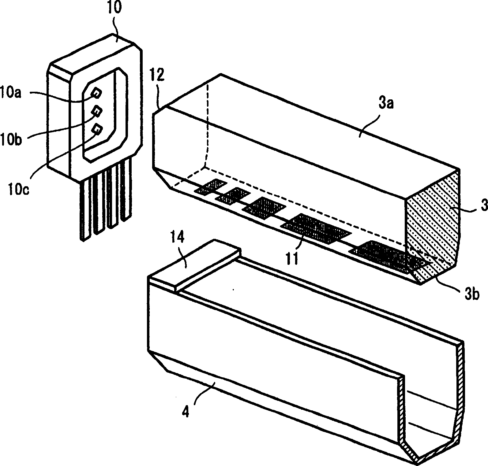
Figure 3
Abstract
Description
technical field
[0001] The present invention relates to an illumination device for illuminating a document, and an image reading device (image sensor) equipped with the illumination device. Background technique
[0002] In facsimile machines, copiers, scanners, etc., an image reading device is installed, and the image reading device includes: an illuminating device incorporating a rod-shaped light guide that irradiates a linear light on an original; Lens array on a linear image sensor.
[0003] Such as patent document 1 and Figure 12 As shown, the general structure of the above-mentioned illuminating device is that a rod-shaped light guide 101 is embedded in a U-shaped housing 100 in cross section, and the light from the light-emitting unit 102 installed at the end of the housing is guided from the end surface of the rod-shaped light guide 101 to the In the rod-shaped light guide, it is totally reflected in the rod-shaped light guide and emitted from the above-mentioned ex...
Examples
Embodiment Construction
[0041] Embodiments of the present invention will be described below with reference to the accompanying drawings. figure 1 It is a cross-sectional view of an image reading device equipped with an illumination device of the present invention, figure 2 is an oblique view of the main part of the lighting device, image 3 It is an exploded oblique view of the main parts of the lighting device.
[0042]The image reading device has a recessed portion 1a and a recessed portion 1b formed in a frame (frame) 1, the upper surface of the recessed portion 1a is closed with a transparent top plate 2 on which a document is placed, and a rod-shaped light guide 3 is housed in a case 4. Line lighting The device 5 is obliquely fixed in the recess 1a, and the substrate 8 including the linear image sensor (photoelectric conversion element) 6 and its driving circuit 7 is installed in the recess 1b below, and further, the same magnification imaging is maintained in the frame body 1. Use a lens ar...