
Aircraft fuselage frame
a fuselage frame and aircraft technology, applied in the field of aircraft fuselage frames, can solve the problems of complex manufacturing and assembly process, and achieve the effects of simple assembly and removal, light weight, and reduced total weight of aircra
Patent Information
- Authority / Receiving Office
- US · United States
- Patent Type
- Patents(United States)
- Current Assignee / Owner
- Publication Date
- 2018-11-13
Smart Images
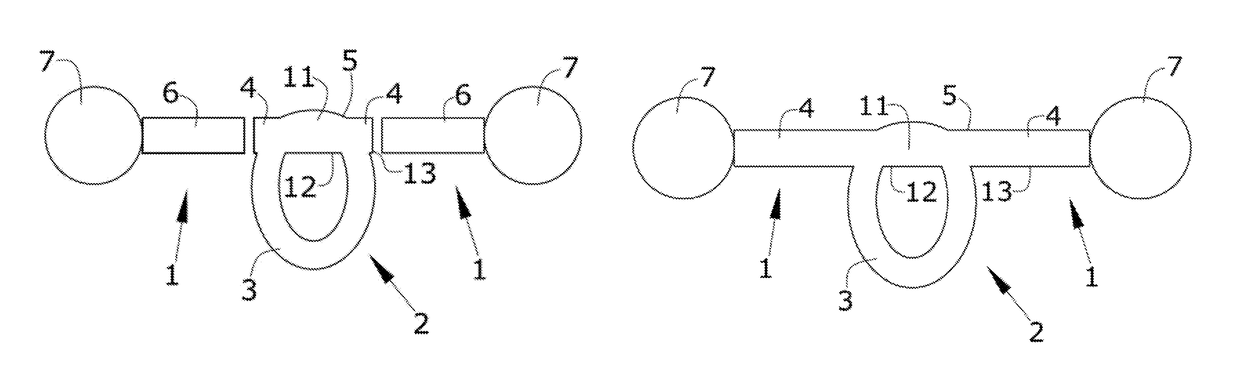
Figure 1 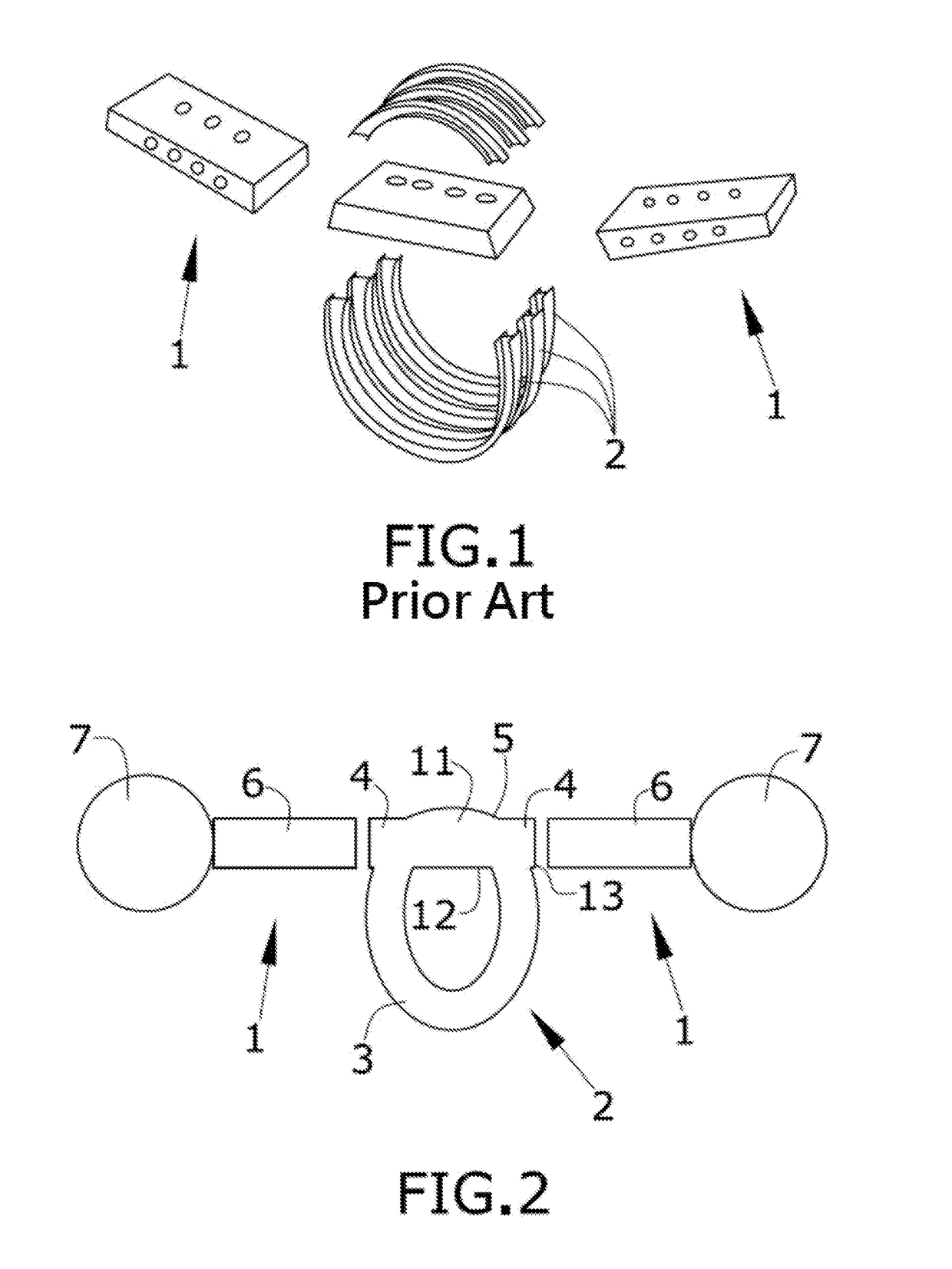
Figure 2 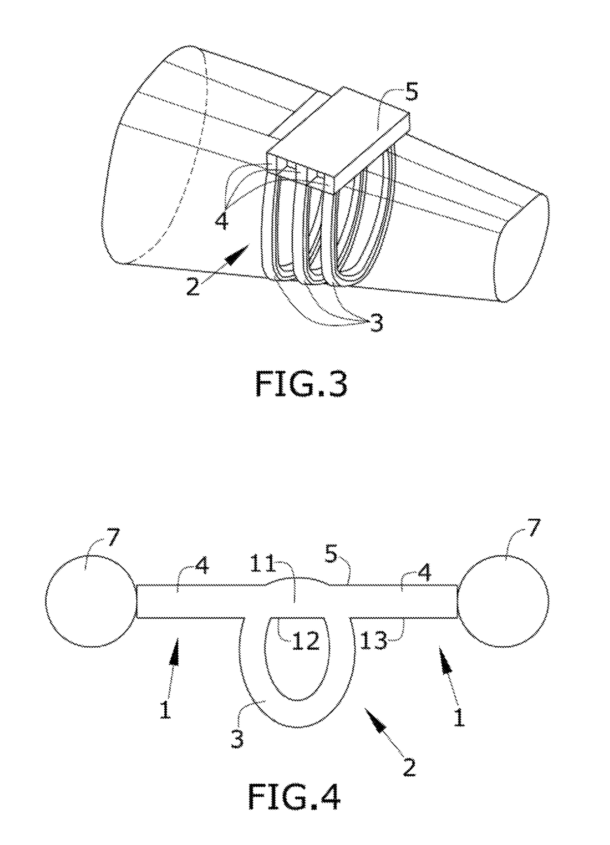
Figure 3
Abstract
Description
RELATED APPLICATION
[0001] This application claims priority to European Patent application No. 14382475.3 filed Nov. 27, 2014, the entirety of which application is incorporated by reference.FIELD OF THE INVENTION
[0002] The present invention refers to a frame of a fuselage of an aircraft and to a section of a fuselage including the frame. The frame is related both to the fuselage structure and to the lifting surfaces located at both sides of the fuselage. The term “lifting surface” includes wings of the aircraft, and associated stabilizing and / or supporting surfaces, such as horizontal stabilisers or pylons for supporting the engines of the aircraft.BACKGROUND OF THE INVENTION
[0003] Known aircraft structures comprise a fuselage and lifting surfaces located at both sides of the fuselage such as wings or pylons for supporting the engines of the aircraft or other supporting structures.
[0004] Known fuselages comprise a plurality of frames, stringers and beams, which act as reinforcing members...
Examples
first embodiment
[0028]In the first embodiment shown in FIGS. 2 and 3, the lateral extensions (4) are further connected to the two extension arms (6). The skin (5) extends over the three frames (2), their corresponding lateral extensions (4) and the extension arms (6). The skin (5) could also extend along the longitudinal direction of the fuselage providing a cruciform shape that should be manufactured in a single panel. Full multi-function of the skin (5) transmitting loads from the fuselage and from the engine support structure allows obtaining a more lightweight structure.
[0029]The extension arms (6) are separated elements therefore there is a joining mean between said extension arm (6) and the lateral extension (4). Said joining means can be tension bolts and / or shear rivets. Although this embodiment also needs a joining means between the lateral extensions (4) and the extension arms (6) it should be noted that the junction between the portion of the lateral extensions (4) and the extensions arm...
second embodiment
[0030]FIGS. 4 and 5a and 5b show the invention wherein the lateral extensions (4) extend until they reach the engines (7). In this embodiment the skin (5) portion of the fuselage is also extended in the lateral directions of the aircraft structure providing a cruciform shape that should be manufactured in a single panel as it also extends in the longitudinal direction of the aircraft. The previously described configuration of the skin (5) would also be applicable to said embodiment.
[0031]In this embodiment the full longitudinal structure of the lifting surface (1) is part of the frame (2), without any disassembly junction between the longitudinal structure (1) and the fuselage, so that the penalty weight due to these junctions is removed.
[0032]This second embodiment could also be applied to a wing, HTP, VTP in which the whole extension arm (4) would be equivalent to a spar of a lateral torsion box that is integrated into the claimed frame (2).
[0033]The additional advantage of this s...