
Laser projection apparatus with liquid-crystal light valves and scanning reading beam
a technology of liquid crystal light and projection apparatus, which is applied in the direction of picture reproducers using projection devices, instruments, non-linear optics, etc., to achieve the effect of enhancing the sharpness of polarization sensitivity, superior image contrast and resolution, and optimizing the enjoyment of its benefits
Patent Information
- Authority / Receiving Office
- US · United States
- Current Assignee / Owner
- Publication Date
- 2005-03-17
- Estimated Expiration
- Not applicable · inactive patent
Smart Images
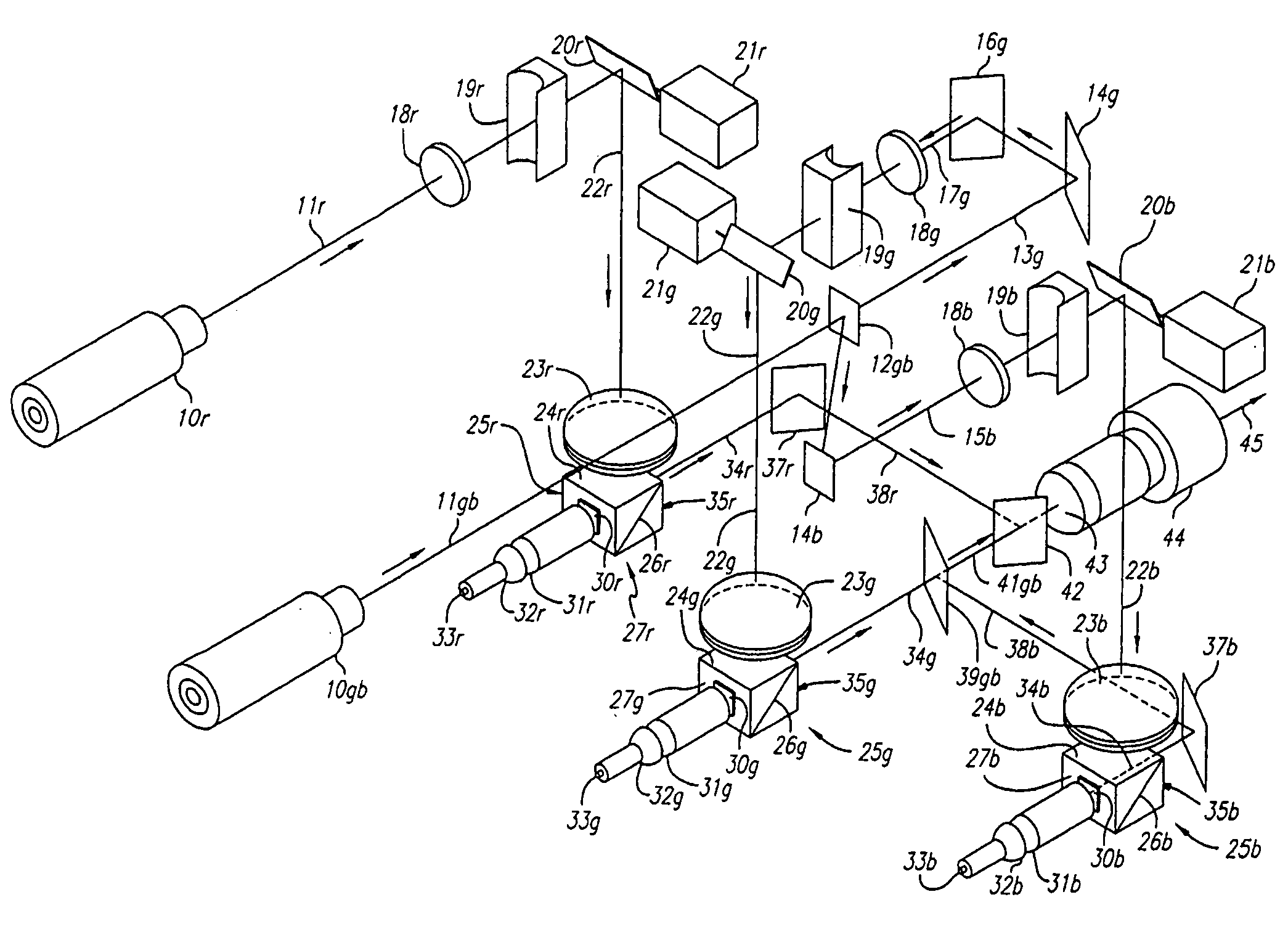
Figure 1 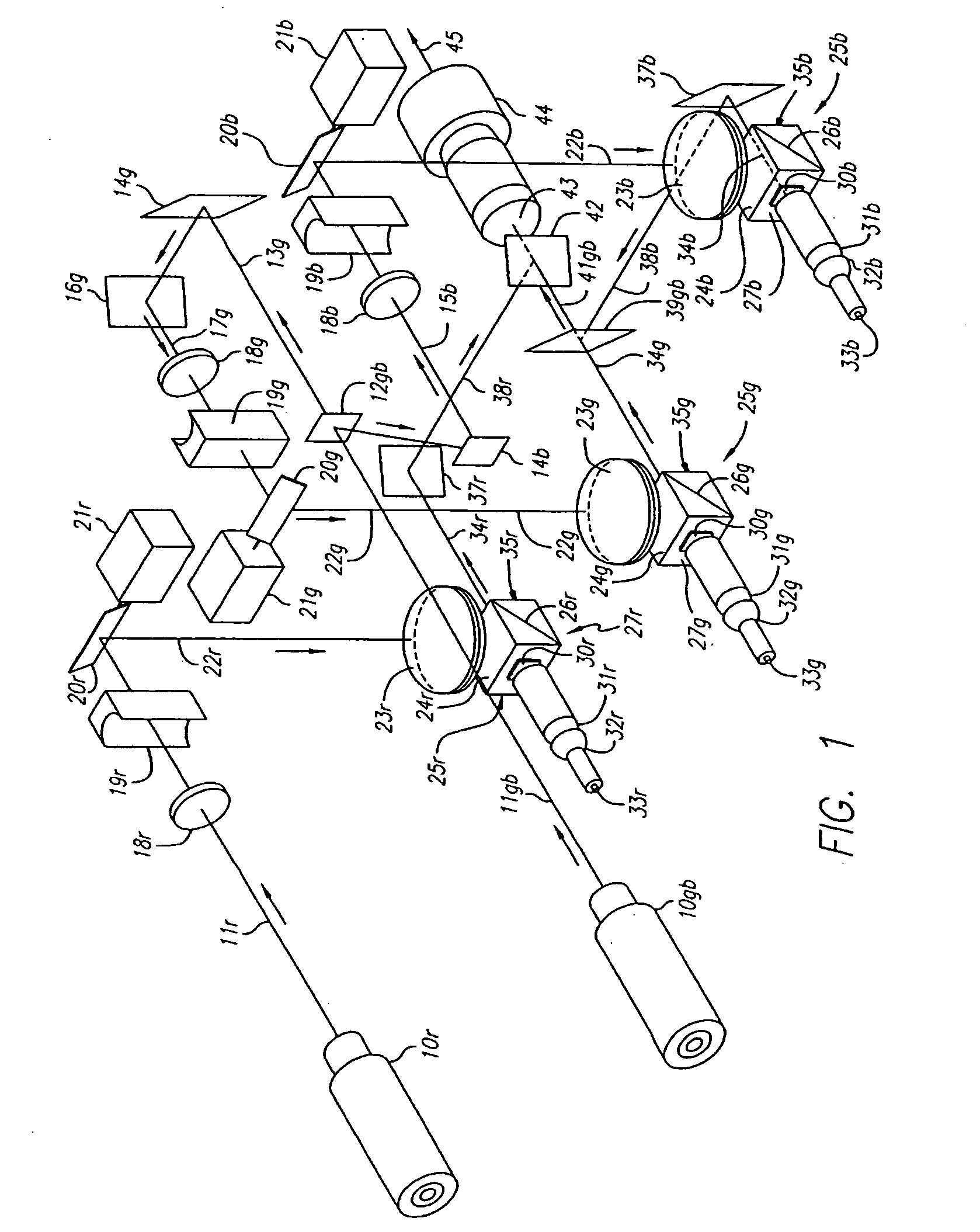
Figure 2 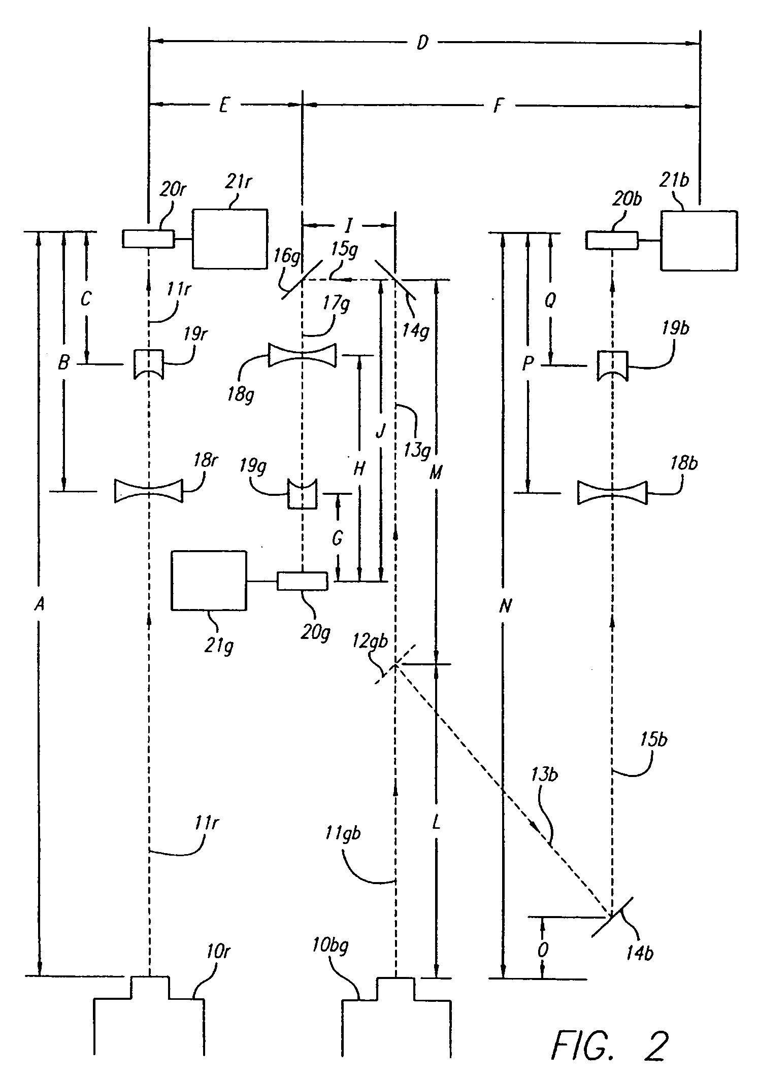
Figure 3
Abstract
Description
BACKGROUND 1. Field of the Invention This invention relates generally to devices for projecting pictures onto large viewing screens; and more particularly to such devices that project laser beams via reflective liquid-crystal light valves to form such pictures. The invention has its most important applications in such projection of moving pictures. 2. Related Art a. Known potential of lasers—Since the advent of the laser, people have been trying to find new ways to use lasers in projecting pictures of one kind or another, for large audiences. This is both natural and reasonable, since lasers offer several important characteristics that are relevant in large-image projection. As will be seen from the following recap of these characteristics, one would expect these characteristics to be responsible for a predominance of laser projection systems in large-screen displays for both video home use and theater-scale displays. Indeed, several powerful large international companies have ...
Examples
Embodiment Construction
a. Overall configuration—Preferred embodiments of my invention, by assigning multiple tasks to certain key elements, achieve the remarkable imaging and energy-usage characteristics described above. They also achieve a degree of simplification and a minimal number of optical surfaces not previously attainable.
Laser-projector apparatus is advantageously laid out in two levels or tiers, one above the other. Either level can be used for the sources 10 (FIGS. 1-4), and the other for the modulation and projection subsystems 23-44, but I prefer to put the sources on top. This configuration is particularly beneficial in allowing very easy exchange of the lasers, for use in image shows calling for higher- or lower-power beams.
Such interchange often demands a change of projection lens 44, too. The lens, however, is generally well forward of the lasers and therefore accessible regardless of the level on which it is mounted.
The suffixes “r”, “g” and “b” on the numbered elements in the dr...