
Quick disconnect hose coupling
Patent Information
- Authority / Receiving Office
- US · United States
- Current Assignee / Owner
- Publication Date
- 2005-03-31
- Estimated Expiration
- Not applicable · inactive patent
Smart Images
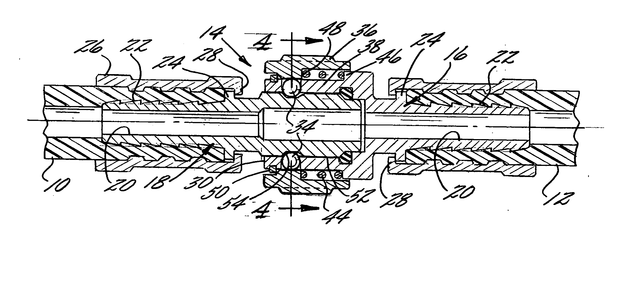
Figure 1 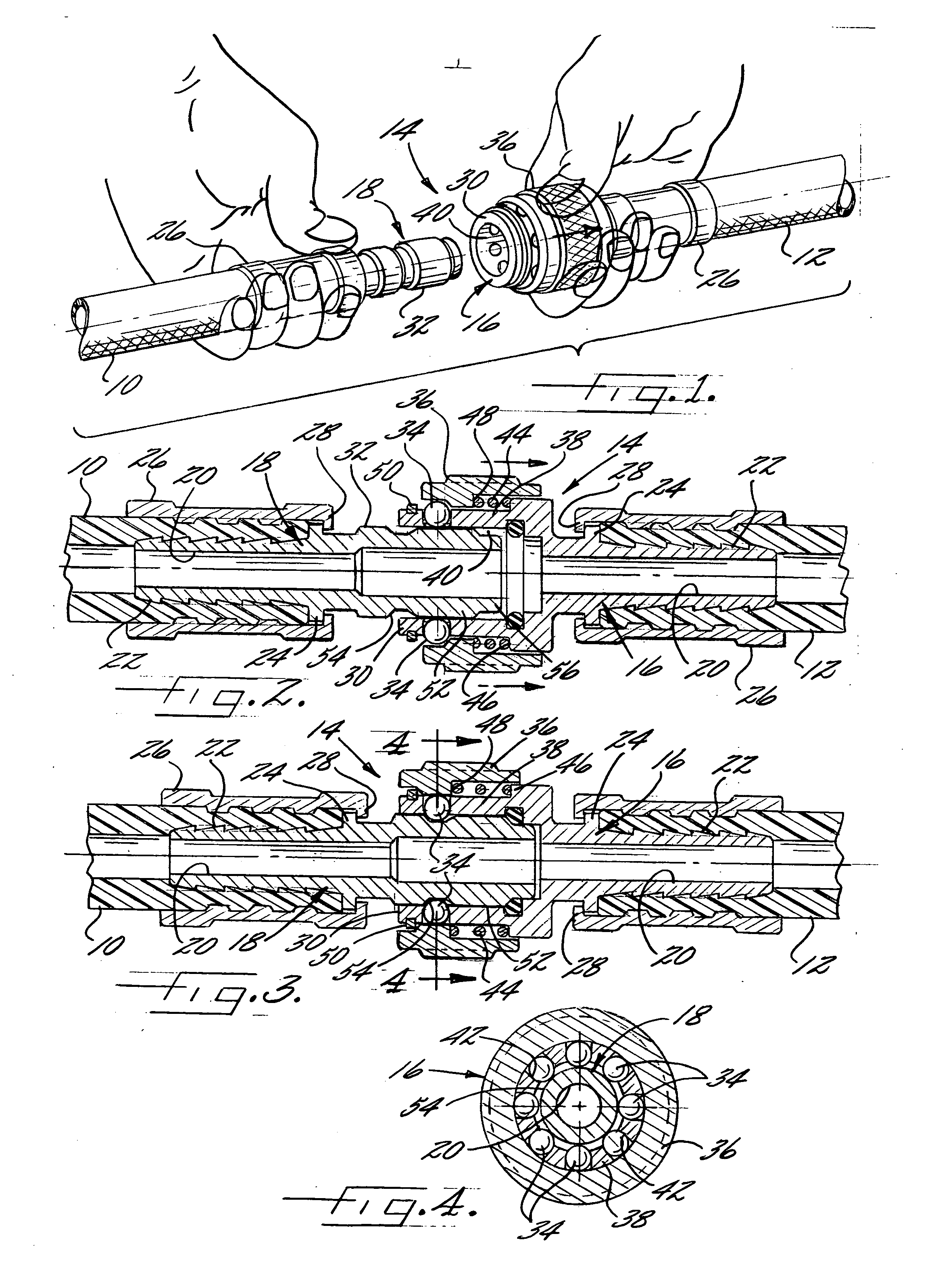
Figure 2 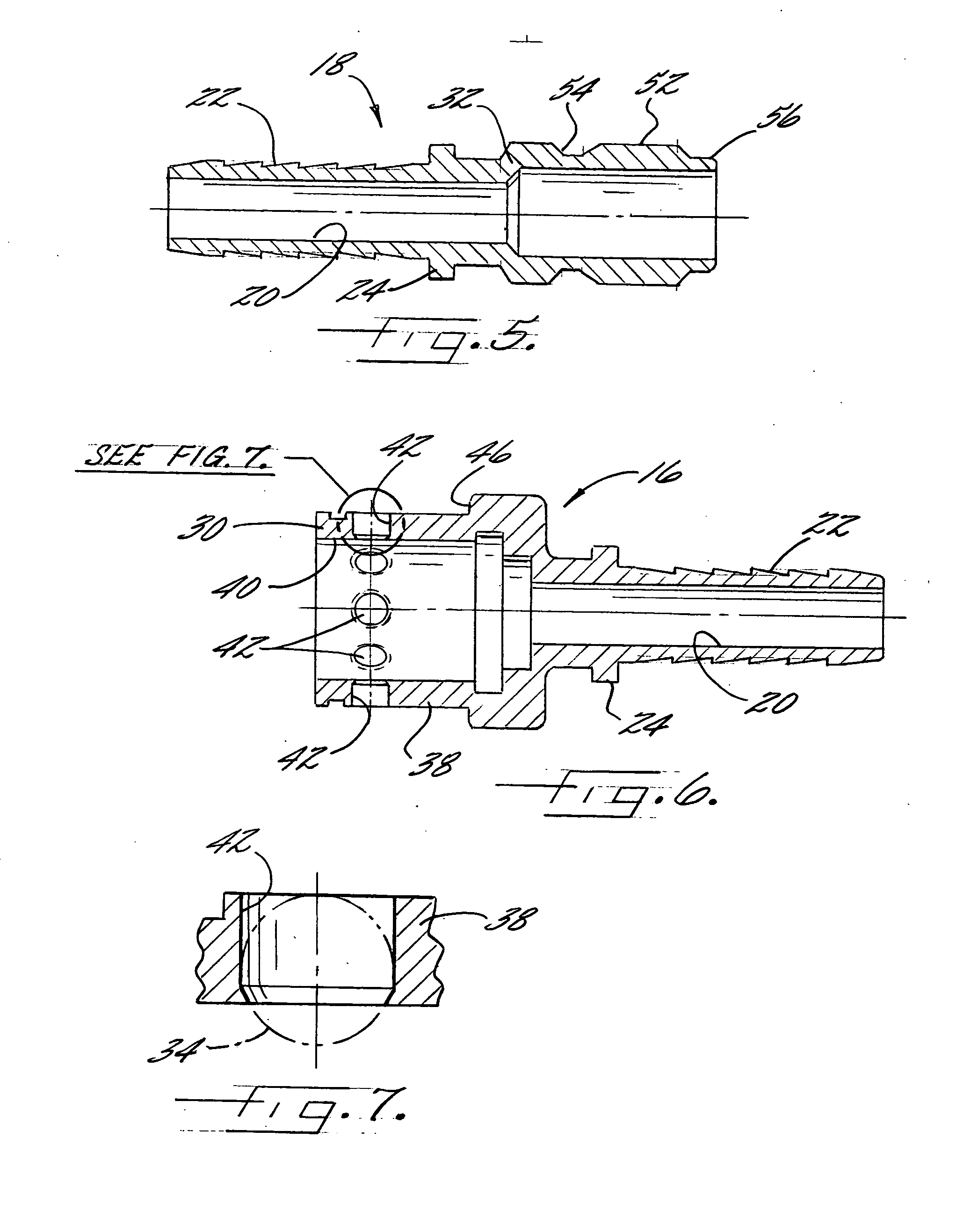
Figure 3
Abstract
Description
FIELD OF THE INVENTION
[0001] The present invention relates generally to liquid hose couplings, and more particularly, to hose couplings which are adapted for quick connection and disconnection. BACKGROUND OF THE INVENTION
[0002] Anyone who has attempted to connect two lengths of hose by screwing together threaded fittings in the ends of the hoses can appreciate how awkward and difficult such connecting procedure can sometimes be. Not only can it be hard to screw the fittings sufficiently tightly by hand to prevent leakage, but over time, rust or contaminants that accumulate on the threaded fittings can prevent the fittings from being easily or completely threaded into engagement with each other.
[0003] To facilitate connection and disconnection of hose lengths together, it is known to use quick disconnect coupling adapters. Such adapters typically comprise a first adapter part that is connected to the male fitting of the hose and a second adapter part that is connected to the femal...
Examples
Embodiment Construction
[0018] Referring now more particularly to the drawings, there is shown in FIG. 1 two illustrative lengths 10, 12 of hose having a quick disconnect coupling 14 in accordance with the invention. Each hose length 10, 12 in this case has a respective hose fitting 16, 18 at the ends of the hose to be connected (see FIGS. 2 and 3). Each of the fittings 16, 18, which preferably are made of metal, is formed with a liquid flow passageway 20 that communicates with the liquid flow passageway of the hose length 10, 12 to which it is connected. It will be understood that the opposite ends of the hose lengths 10, 12 also may be provided with appropriate fittings, either of a conventional type, or a quick disconnect type in accordance with the invention.
[0019] Each hose fitting 16, 18 in this case has a respective inwardly extending ribbed shank 22 that is forcefully positioned into the end of a hose length up to and against a radial locating flange 24 of the fitting as shown in FIGS. 2 and 3. An...