
Ink cartridge attachment/detachment device, recording apparatus, liquid ejection apparatus, and liquid container
a technology of ink cartridges and attachment devices, which is applied in printing, roofing, construction, etc., can solve the problems of not providing the large pressing force required to cope with an ink cartridge unit of a single package, imposing a natural force on the ink jet printer, and unable to apply such a large pressing for
Patent Information
- Authority / Receiving Office
- US · United States
- Current Assignee / Owner
- Publication Date
- 2005-08-04
Smart Images
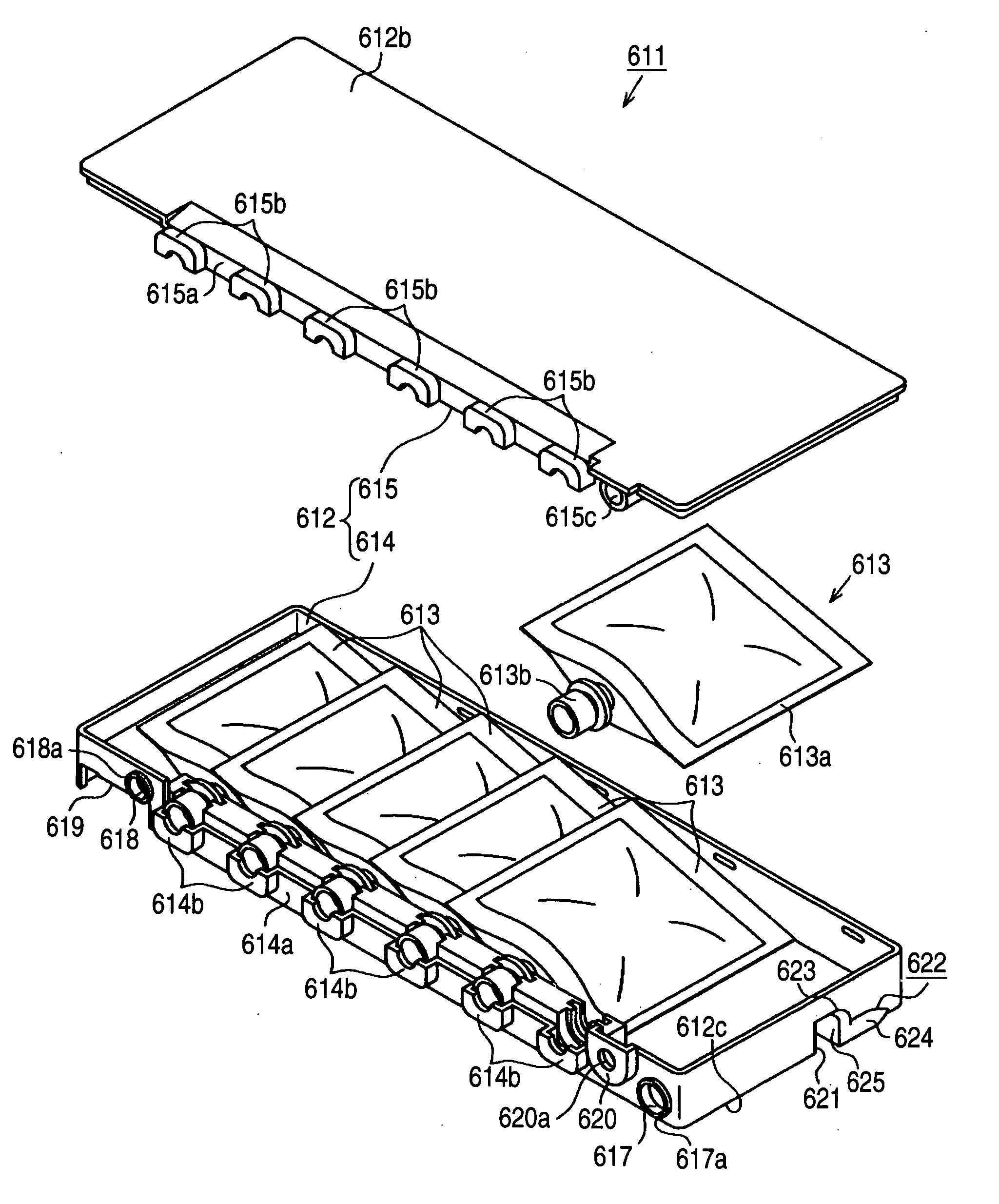
Figure 1 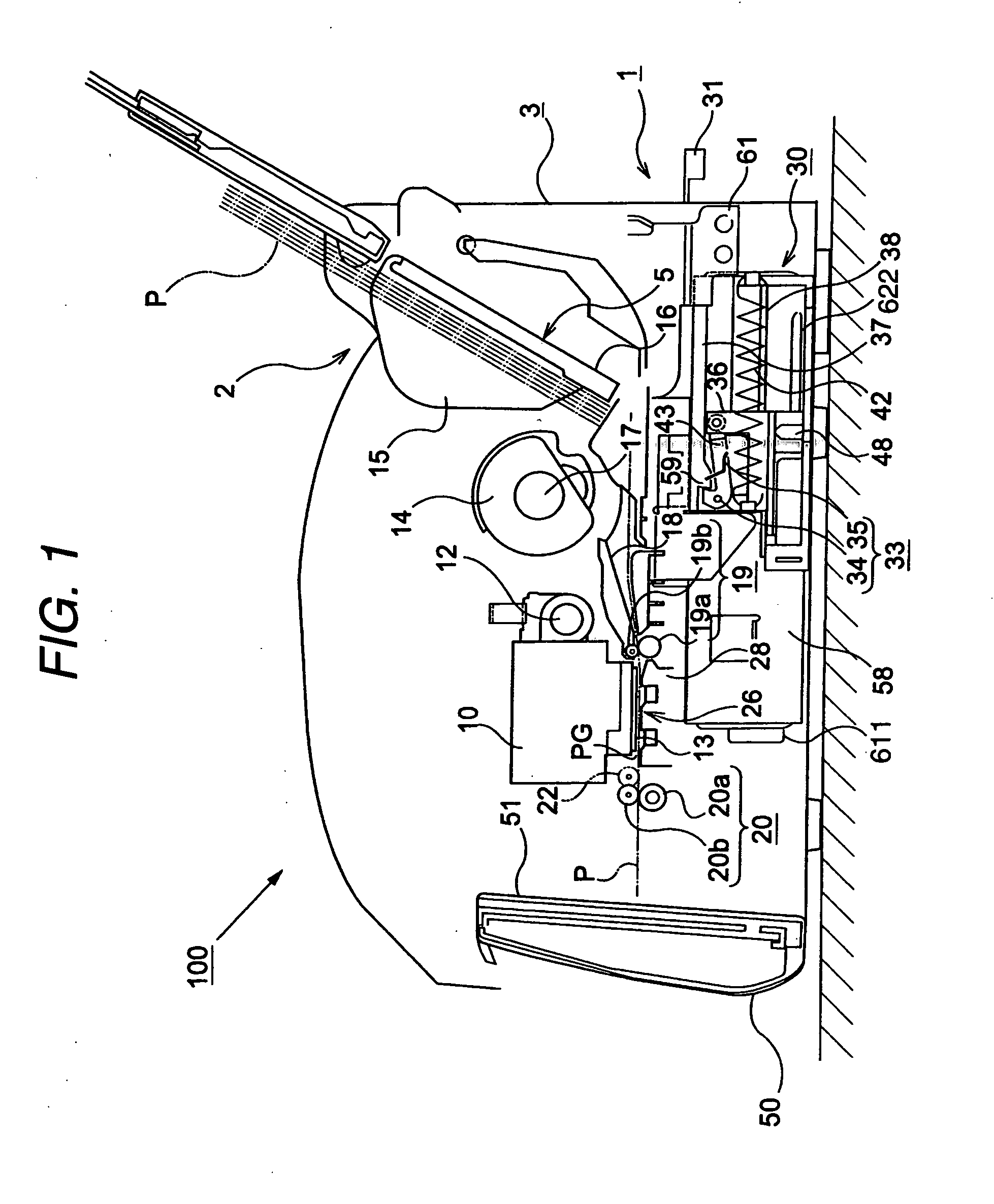
Figure 2 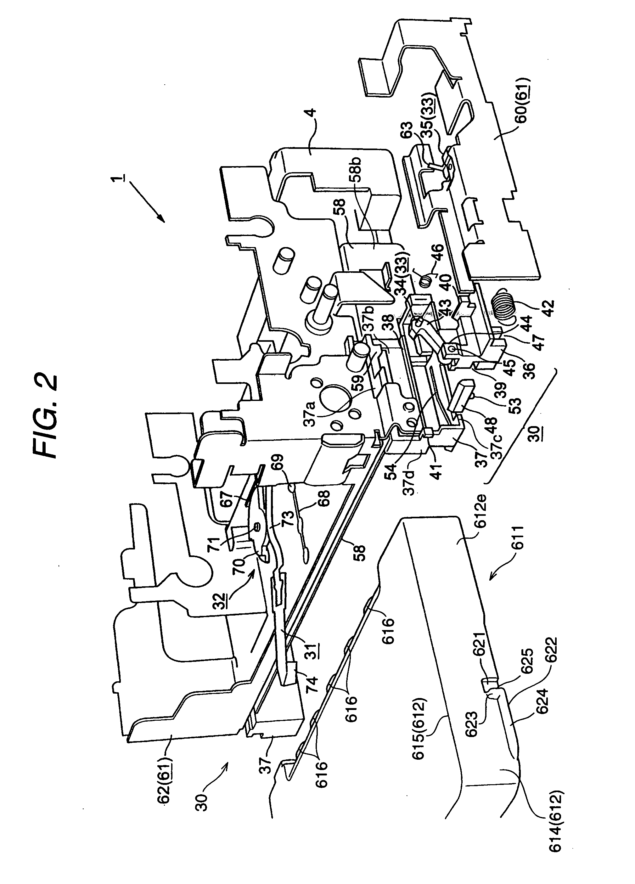
Figure 3
Abstract
Description
BACKGROUND OF THE INVENTION
[0001] The present invention relates to an ink cartridge attachment / detachment device that slides an ink cartridge horizontally to load it into the main body of a recording apparatus, and a recording apparatus comprising this attachment / detachment device. The present invention also relates to a liquid ejection apparatus, such as an ink jet recording apparatus, that discharges (ejects) a liquid, such as ink, from a recording head and records on (attaches the liquid to) recording material (an ejected liquid target material), and a liquid cartridge attachment / detachment device provided for the liquid ejection apparatus. The present invention further relates to a liquid container (liquid cartridge) including an ink cartridge.
[0002] In this case; such a liquid ejection apparatus includes not only a recording apparatus, such as a printer, a copier or a facsimile machine, that employs an ink jet recording head and that, by ejecting ink, records images on a reco...
Examples
first modification
[0224] (First Modification)
[0225]FIG. 16 is a rear view of an ink jet printer where a lid member is closed. FIG. 17 is a rear view of the ink jet printer where the lid member is open and a lever arm is located at a set position. FIG. 18 is a rear view of an ink jet printer where the lid member is open and the lever arm is located at a reset position. FIG. 19 is an enlarged, oblique perspective bottom view of the periphery of ink cartridge erroneous insertion prevention means. FIGS. 20A, 20B and 20C are bottom views of the operating state of the ink cartridge erroneous insertion prevention means when the ink cartridge is normally inserted. FIGS. 21A and 21B are bottom views of the operating state of the ink cartridge erroneous insertion prevention means when the ink cartridge is erroneously inserted. FIG. 22 is a bottom view of the operating state of the ink cartridge erroneous insertion prevention means when the ink cartridge is inserted while only a cartridge holding means on one s...
second modification
[0232] (Second Modification)
[0233]FIG. 23 is a perspective view of an ink cartridge erroneous insertion prevention unit including a collision avoiding unit. FIGS. 24A, 24B and 24C are side cross-sectional views of the operating state of the ink cartridge erroneous insertion prevention unit wherein an ink cartridge is erroneously inserted while a lever arm is located at a position other than a reset position. FIGS. 25A, 25B and 25C are side cross-sectional views of the operating state of the ink cartridge erroneous insertion prevention unit wherein an ink cartridge is inserted while the lever arm is located at the reset position. FIGS. 26A, 26B and 26C are side cross-sectional views of the operating state of an ink cartridge erroneous insertion prevention unit that does not include a collision avoiding unit, wherein an ink cartridge is erroneously inserted while the lever arm is located at a position other than the reset position. FIGS. 27A, 27B and 27C are side cross-sectional views...
third modification
[0239] (Third Modification)
[0240]FIG. 28 is a perspective view of an ink cartridge erroneous insertion unit when a lever arm is located at a position other than the reset position. FIG. 29 is a perspective view of the ink cartridge erroneous insertion prevention unit when the lever arm is located at the reset position. FIG. 30 is an exploded perspective view of the ink cartridge erroneous insertion prevention unit. FIG. 31 is a rear view of the ink cartridge erroneous insertion prevention unit when the lever arm is located at a position other than the reset position. FIG. 32A is a plan view of the ink cartridge erroneous insertion prevention unit in the state wherein the lever arm is located at a position other than the reset position, and FIG. 32B is a plan view of the ink cartridge erroneous insertion prevention unit in the state wherein the lever arm is located at the reset position. FIGS. 33A and 33B are oblique perspective bottom view of the ink cartridge erroneous insertion pr...