
HDMI plug connector
a multimedia interface and plug connector technology, applied in the direction of coupling device connections, coupling protective earth/shielding arrangements, contact members penetrating/cutting insulation/cable strands, etc., can solve the problem of increasing the number of installation components, dvi is not absolutely perfect, and the number of connection lines is not enough. problem, to achieve the effect of high fidelity video signal, less cable, and best quality
Patent Information
- Authority / Receiving Office
- US · United States
- Patent Type
- Applications(United States)
- Current Assignee / Owner
- Publication Date
- 2005-08-25
Smart Images
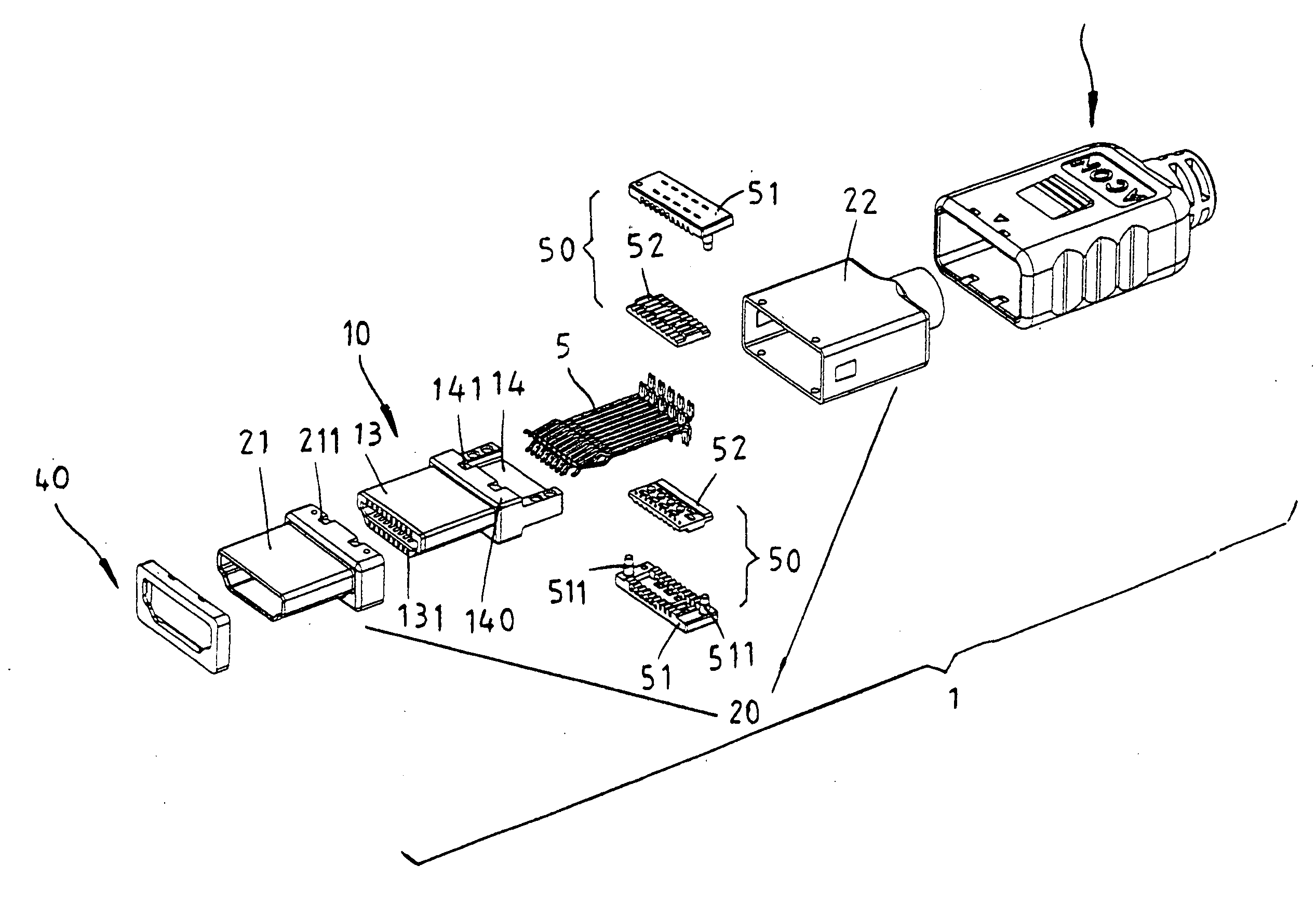
Figure 1 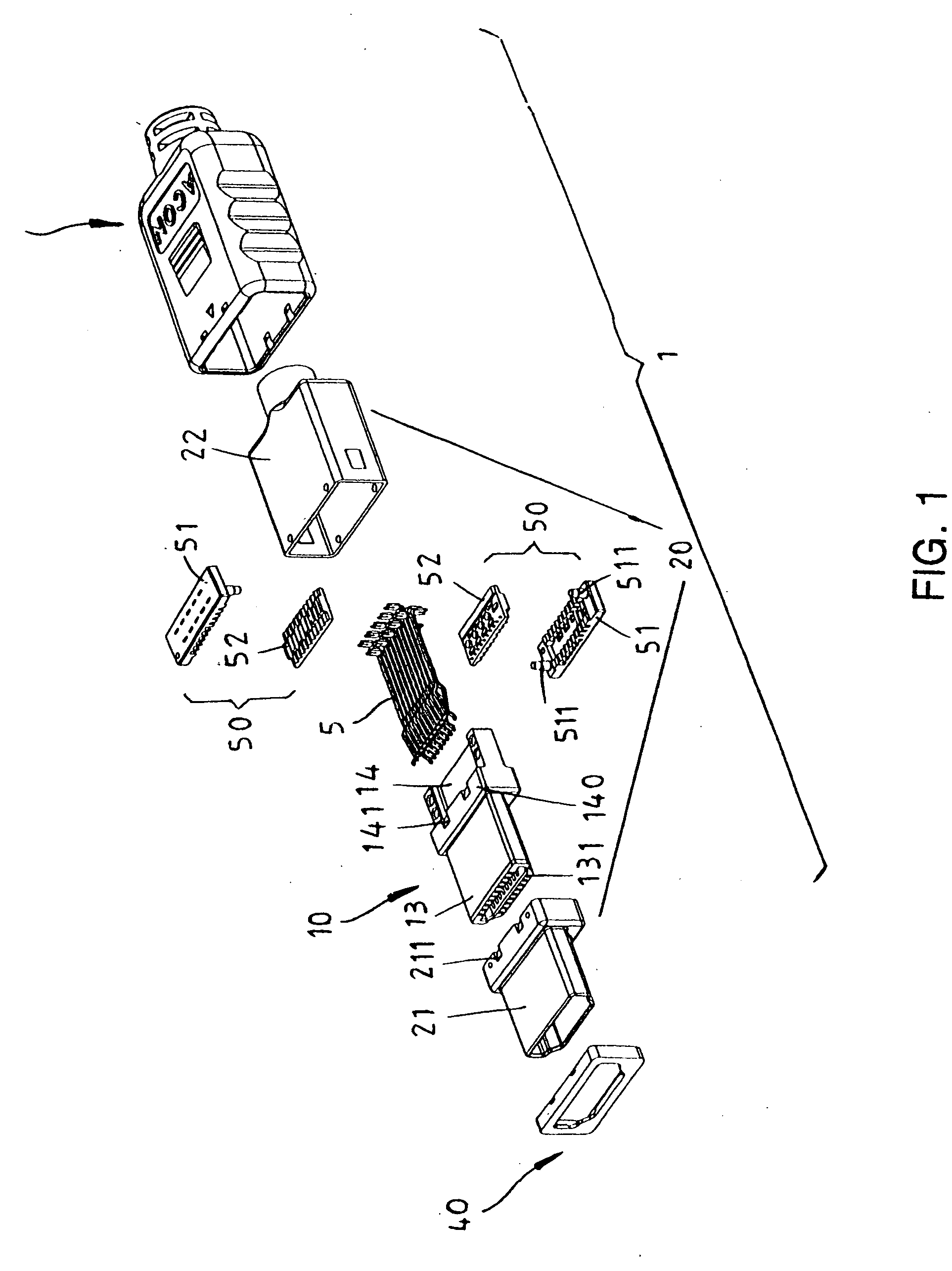
Figure 2 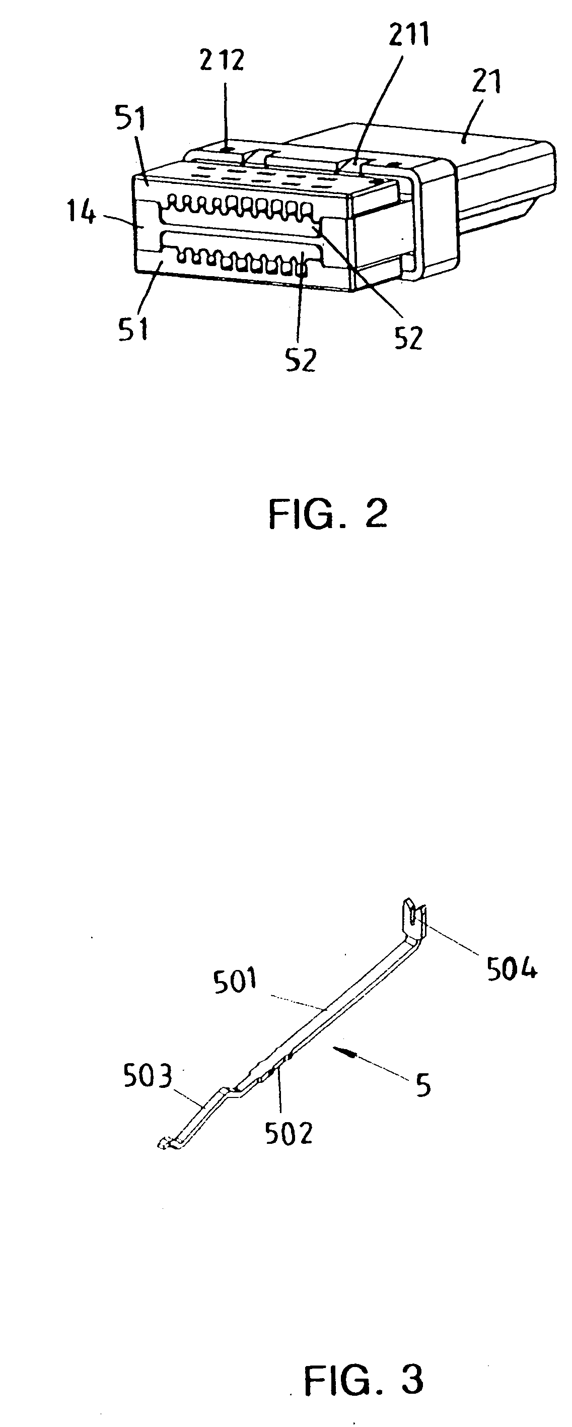
Figure 3
Abstract
Description
BACKGROUND OF THE INVENTION
[0001] 1. Field of the Invention
[0002] The present invention relates to a high definition multimedia interface (HDMI) connector, and more specifically to a small connector utilized in digital TV, DVD player, deck-top box (video signal converter), and other digital Audio / Video (AV) product.
[0003] 2. Description of the Related Art
[0004] LCD in nowadays has become a most popular output device for Audio / Video (AV) product. Since it plays an important role in the products of modern PC monitor and TV display, and in the light of connector for digital signal transmission has become a mainstream product in LCD industries, the HDMI connector of the invention is thus created to serve this purpose.
[0005] The HDMI (High Definition Multimedia Interface) is a transmission interface utilized for the transmission of a high definition multimedia digital signal including high fidelity image and multi-channel audio signal. The earliest specification of the HDMI was esta...
Examples
Embodiment Construction
[0018] With the reference to FIG. 1, wherein a HDMI plug connector 1 comprises an insulated housing 10, a metallic cover shell 20, a plastic outer shell 30, and a front cover 40, wherein the structure of the insulated housing 10 consists of an insertion front 13 at front part and a retaining platform 14 at rear part, furthermore, the insulated housing 10 also provides an insertion holder for the terminal 5.
[0019] The insertion front 13 is a flat projected body, which provides two rows of terminal receiving slots 131 aligned at its top and bottom side extended throughout the portion from the insertion front 13 at the front part to the retaining platform at the rear part, and utilizes the curved contour shape at the bottom of both sides of the projected body to form an error proof design.
[0020] The retaining platform 14 is formed mainly by a horizontal T shape block combined with the insertion front 13, and a plurality of protrusions 141 are furnished on the top and bottom ends for ...