
Steering column for motor vehicle
a technology for steering columns and motor vehicles, applied in the direction of steering columns, steering parts, vehicle components, etc., can solve the problems of easy slippage of the clamp section when a great force is applied, and achieve the effect of high reliability and convenient operation
Patent Information
- Authority / Receiving Office
- US · United States
- Patent Type
- Applications(United States)
- Current Assignee / Owner
- Publication Date
- 2005-10-06
- Estimated Expiration
- Not applicable · inactive patent
Smart Images
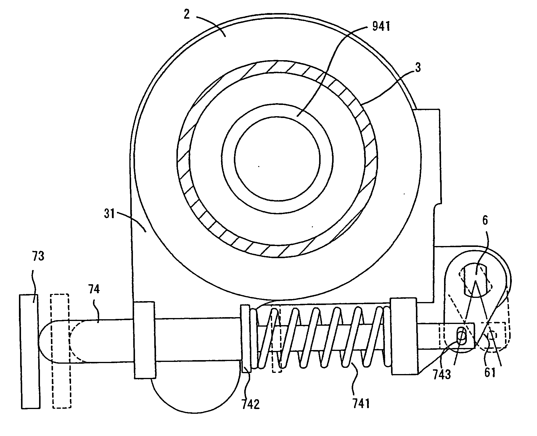
Figure 1 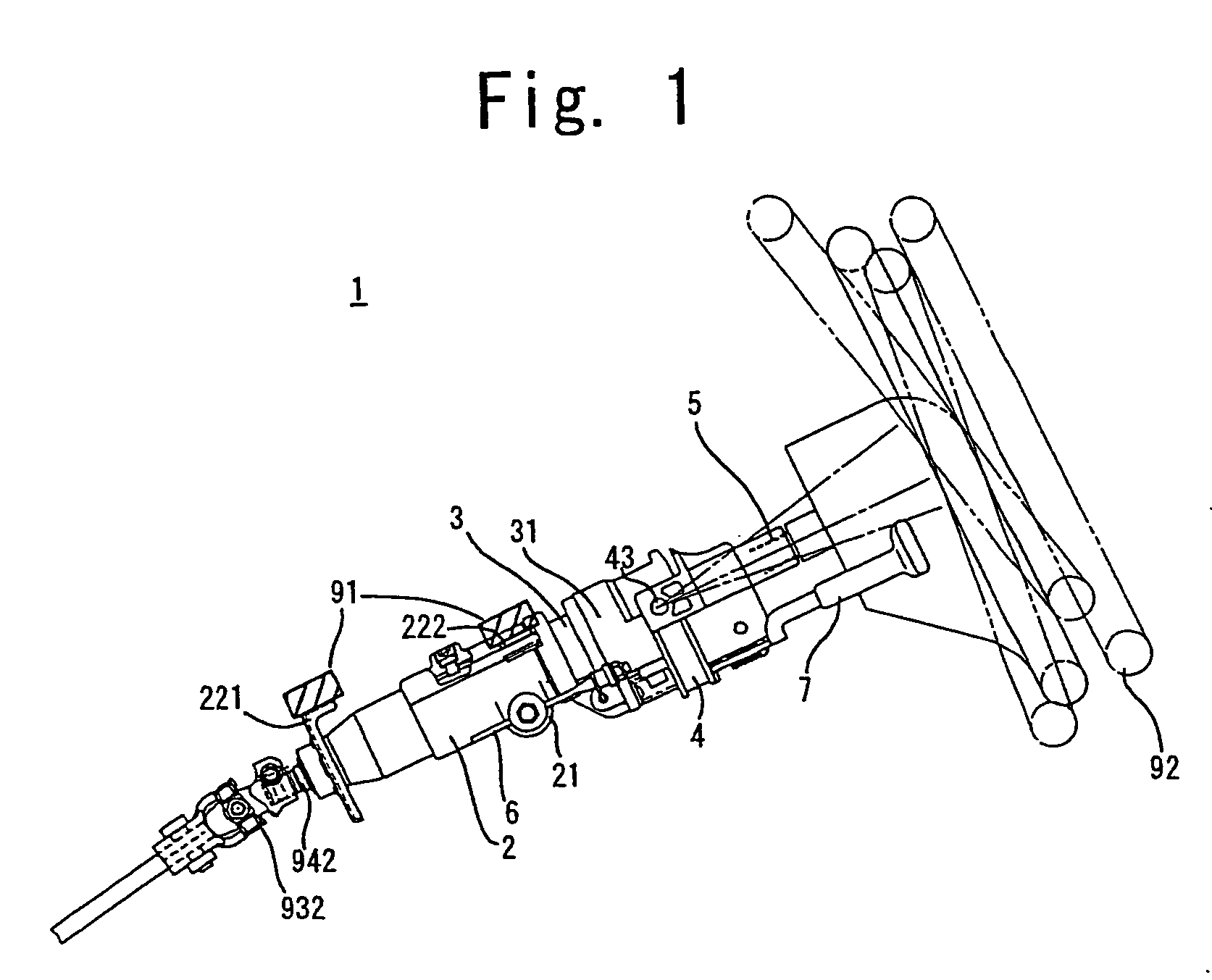
Figure 2 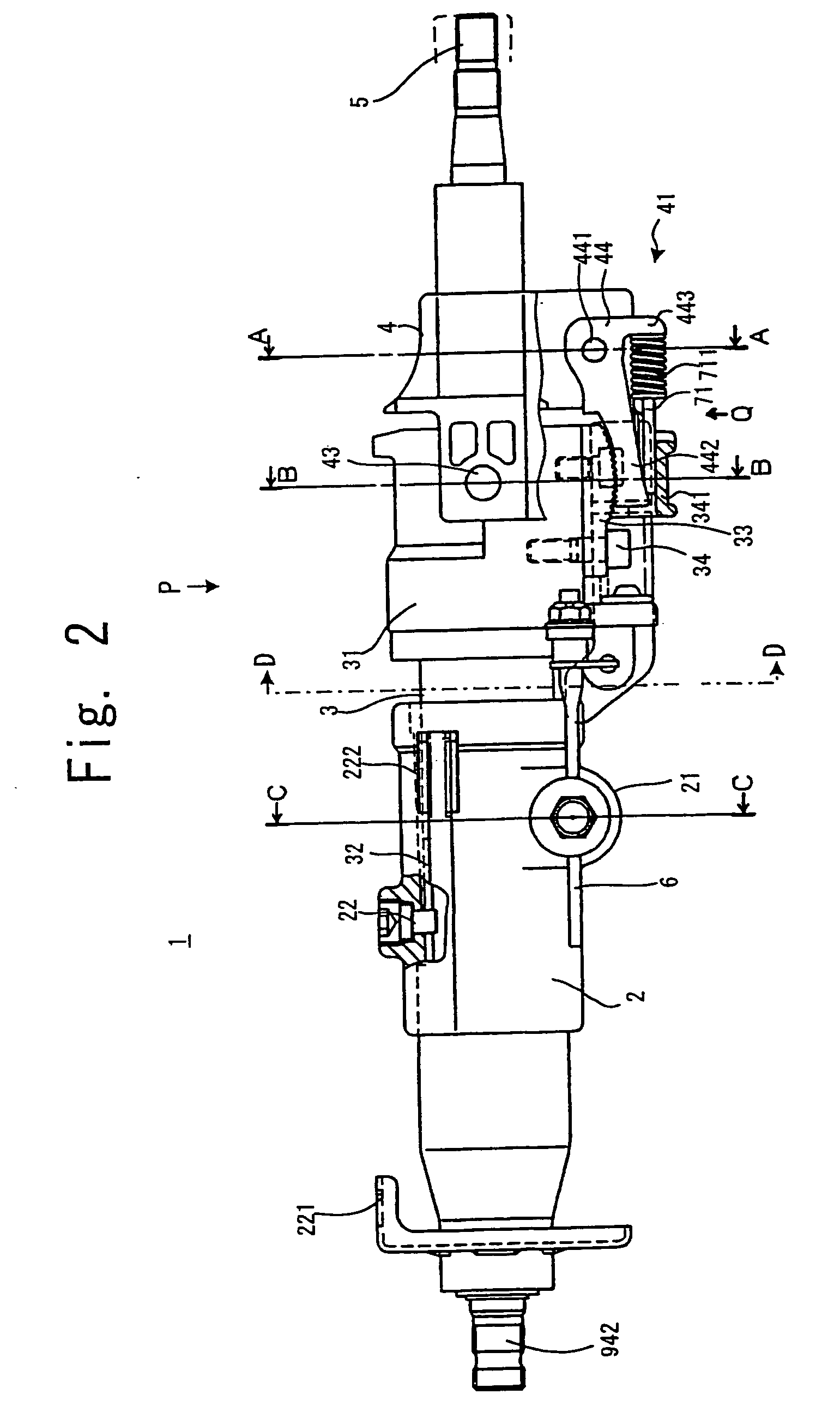
Figure 3
Abstract
Description
[0001] This application is based on and claims the benefit of Applications Nos. 2002-146694, No. 2002-245636, and No. 2002-273484 filed in Japan, the contents of which are hereby incorporated by reference. In addition, this application is a continuation-in-part of and claims the benefit of co-pending U.S. patent application Ser. No. 10 / 440,813, filed May 19, 2003.BACKGROUND OF THE INVENTION
[0002] 1. Field of the Invention
[0003] This invention relates to a steering column, and more particularly, to a steering column for motor vehicle having a telescopic mechanism and a tilting mechanism.
[0004] 2. Description of Related Art
[0005] The telescopic mechanism and the tilting mechanism of the steering column aim at adjusting the back-and-forth position and tilt angle of a steering wheel to the easiest-to-manipulate position according to the driver's body form and taste.
[0006] The telescopic mechanism and the tilting mechanism have a clamp / unclamp mechanism for adjusting the level and t...
Examples
first embodiment
General Outline
[0037]FIG. 1 is an outside view of a steering column 1 according to the first embodiment of this invention. The steering column 1 has a fixed column member 2, a moving column member 3, a column head 31, a tilt head 4, a wheel shaft 5, a column clamp 21, a tilt head clamp 41 (see FIG. 2), an control lever 7, and a mechanical transmission apparatus.
[0038] The fixed column member 2 is fitted with mounting sections 221 and 222 for mounting to the vehicle body 91. On the fixed column member 2 the moving column member 3 is supported unrotatably around the center axis and movably in the direction of the center axis. The column head 31 is mounted on one end of the moving column member 3. On the column head 31, the tilt head 4 is supported in such a manner that it can tilt on the center of a tilt center axis 43. On the tilt head 4 the wheel shaft 5 is rotatably supported. A steering wheel 92 is fixed on one end of the wheel shaft 5.
[0039] On the column head 31, a column cl...
second embodiment
[0067] The steering column 1 of the second embodiment, except the structure of the control lever 7, has a structure common to that of the steering column of the first embodiment. To avoid redundancy of explanation, only the control lever 7 and related structures which are different from the first embodiment will be explained, using the same reference numerals as those used in the explanation of the first embodiment.
[0068]FIG. 12 is a top view, partly cut away, of the steering column 1 according to the second embodiment. FIG. 12 corresponds to FIG. 3 in the first embodiment. The control lever 7 in the second embodiment has a control lever body 705 and a control lever end 701 pivotally supported thereon. The control lever end 701 is foldable in between the operating position and the retreat position. In the operating position, the control lever 7 is operable by other fingers with the thumb left on the steering wheel 92. In the retreat position, the control lever is apart from the ste...
third embodiment
[0072] The steering column 1 of the third embodiment has a structure substantially common to the steering column of the first embodiment excepting the provision of the cowl 35 and the structure of the control lever 7. To avoid redundancy of explanation, only the cowl 35, the control lever 7 and related structures which are different from the first embodiment will be explained; the same reference numerals as those used in the explanation of the first embodiment will be used.
[0073]FIG. 13 is a top view, partly cut away, of the steering column 1 according to the third embodiment. FIG. 13 corresponds to FIG. 3 in the first embodiment. The cowl 35 is a cover for covering the tilt head 4 and the moving column member 3, and is fixed on the tilt head 4. The cowl 35 has a shaft hole 3 through which the wheel shaft 5 is mounted, and a lever hole 352 through which the control lever 7 is mounted.
[0074] In the side of the cowl 35, a dent is formed so that a part of the control lever end 701 fo...