
Orthopedic fixation device
Patent Information
- Authority / Receiving Office
- US · United States
- Patent Type
- Applications(United States)
- Current Assignee / Owner
- Publication Date
- 2006-01-05
- Estimated Expiration
- Not applicable · inactive patent
Smart Images
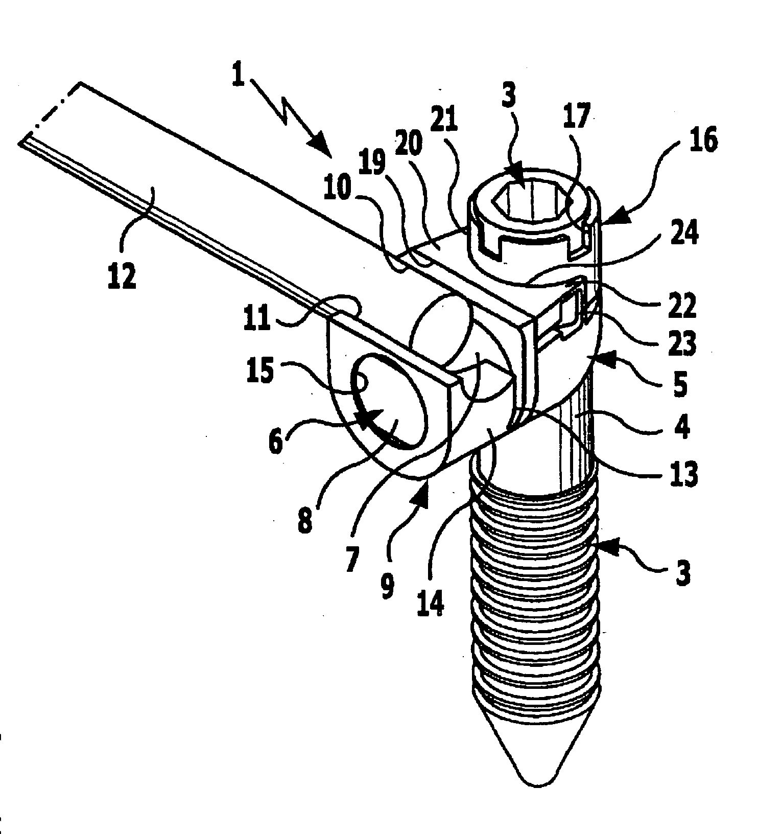
Figure 1 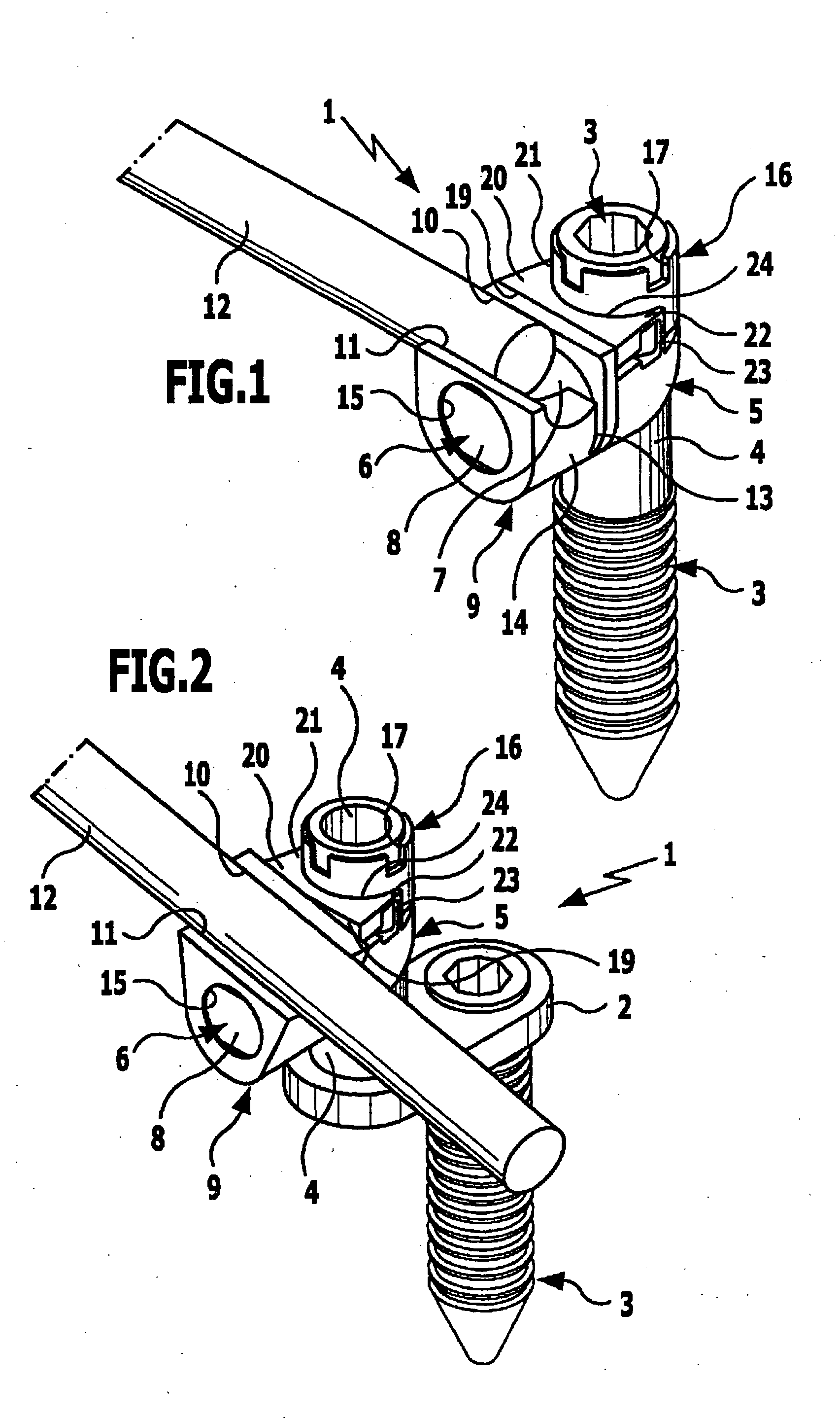
Figure 2 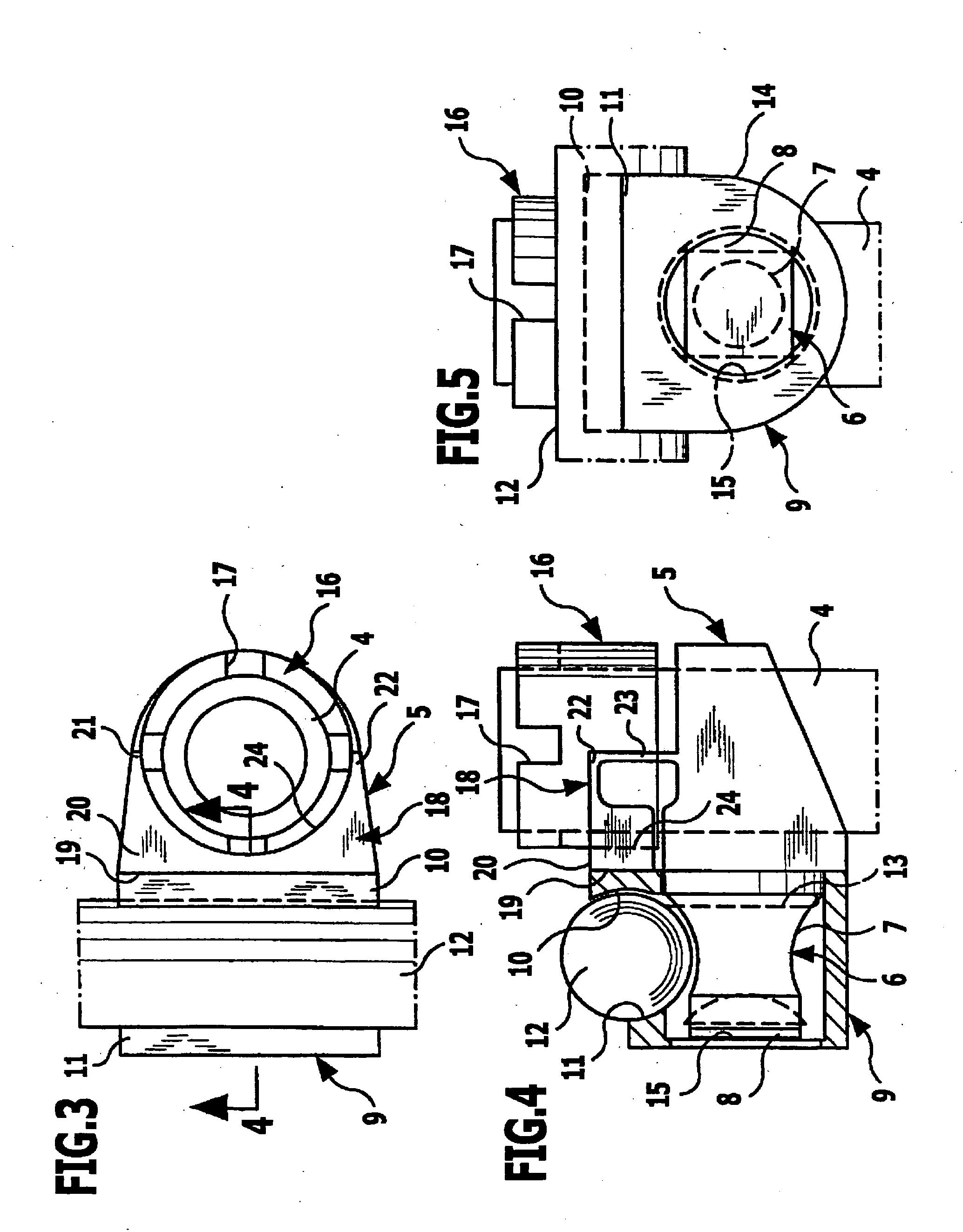
Figure 3
Abstract
Description
[0001] This application is a continuation of international application number PCT / EP2002 / 009878 filed on Sep. 4, 2002.
[0002] The present disclosure relates to the subject matter disclosed in international application No. PCT / EP2002 / 09878 of Sep. 4, 2002, which is incorporated herein by reference in its entirety and for all purposes.BACKGROUND OF THE INVENTION
[0003] The invention relates to an orthopedic fixation device for securing a rod-like fixation element, with two clamping jaws which can be moved relative to one another and which, when brought together, clamp the fixation element between them.
[0004] To fix bones or bone parts relative to one another, for example in the region of the spinal column, it is known to use rod-like fixation elements which, at different locations, are clamped between clamping jaws, and these clamping jaws are then connected by bone screws or similar fixation means to the bones or bone fragments to be fixed (WO 97 / 06742; U.S. Pat. No. 5,741,255; U.S....
Examples
Embodiment Construction
[0061] The orthopedic fixation device 1 shown in FIGS. 1 to 8 is, in the illustrative embodiment in FIG. 1, fitted onto the shaft of a bone screw 3 whereas, in the illustrative embodiment in FIG. 2, it is fitted onto a sleeve-shaped, cylindrical mounting body 4 which is disposed on the bone screw 3 in a laterally offset position by way of a transverse support 2. In the following description, both the shaft of the bone screw 3 and the cylindrical mounting body 4 of the transverse support 2 are referred to jointly as mounting body 4, although it will be appreciated that the described orthopedic fixation device 1 can be fitted onto a wide variety of pin-shaped, shaft-shaped or sleeve-shaped mounting bodies.
[0062] A support piece 5 is pushed onto the mounting body 4 from above, tightly surrounds the mounting body 4 and is freely rotatable thereon. This support piece 5 has a mounting shaft 6 which protrudes from it in a direction transverse to the longitudinal direction of the mounting ...