
Transfer unit for transferring glass articles
Patent Information
- Authority / Receiving Office
- US · United States
- Current Assignee / Owner
- Publication Date
- 2006-02-23
- Estimated Expiration
- Not applicable · inactive patent
Smart Images
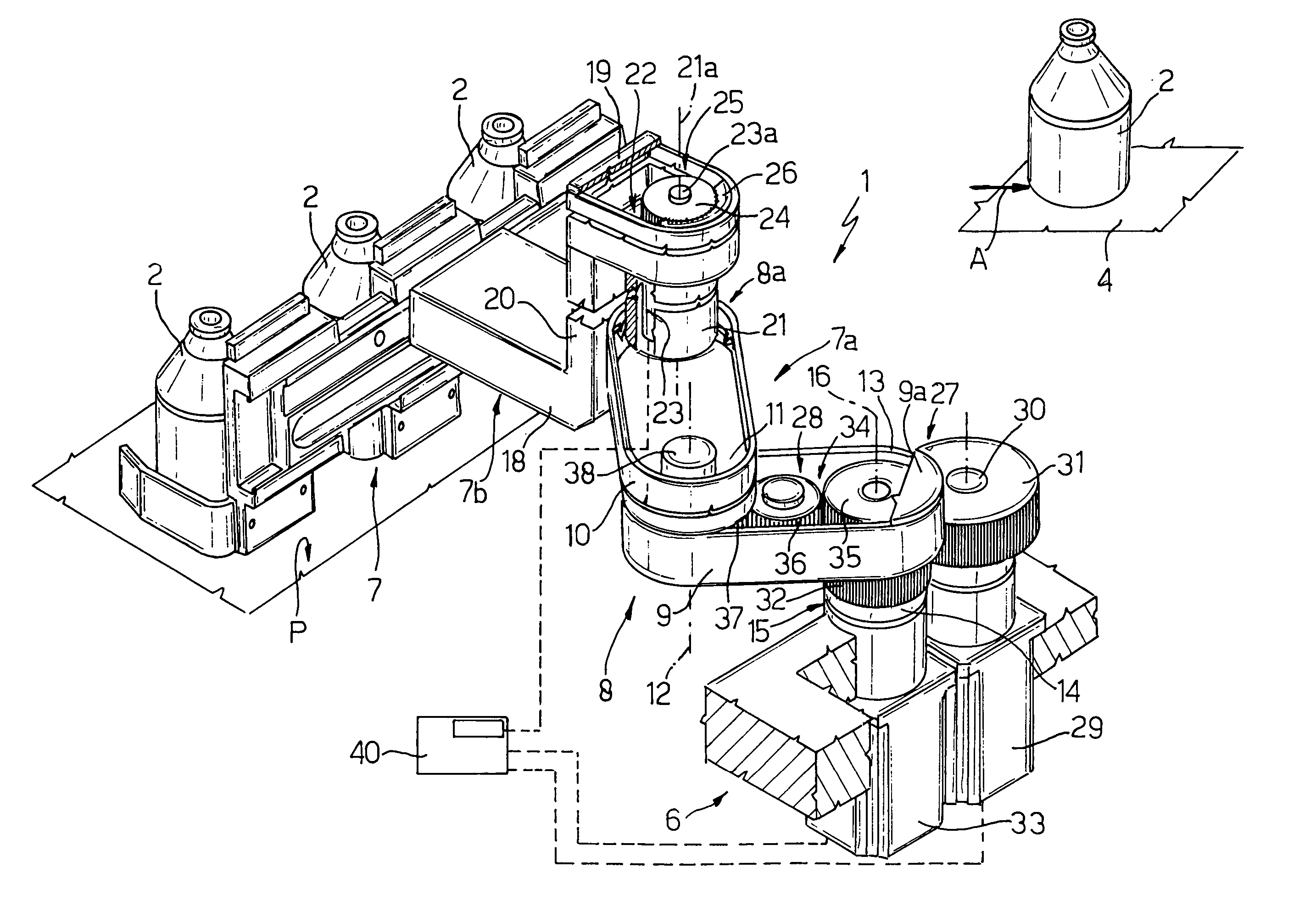
Figure 1 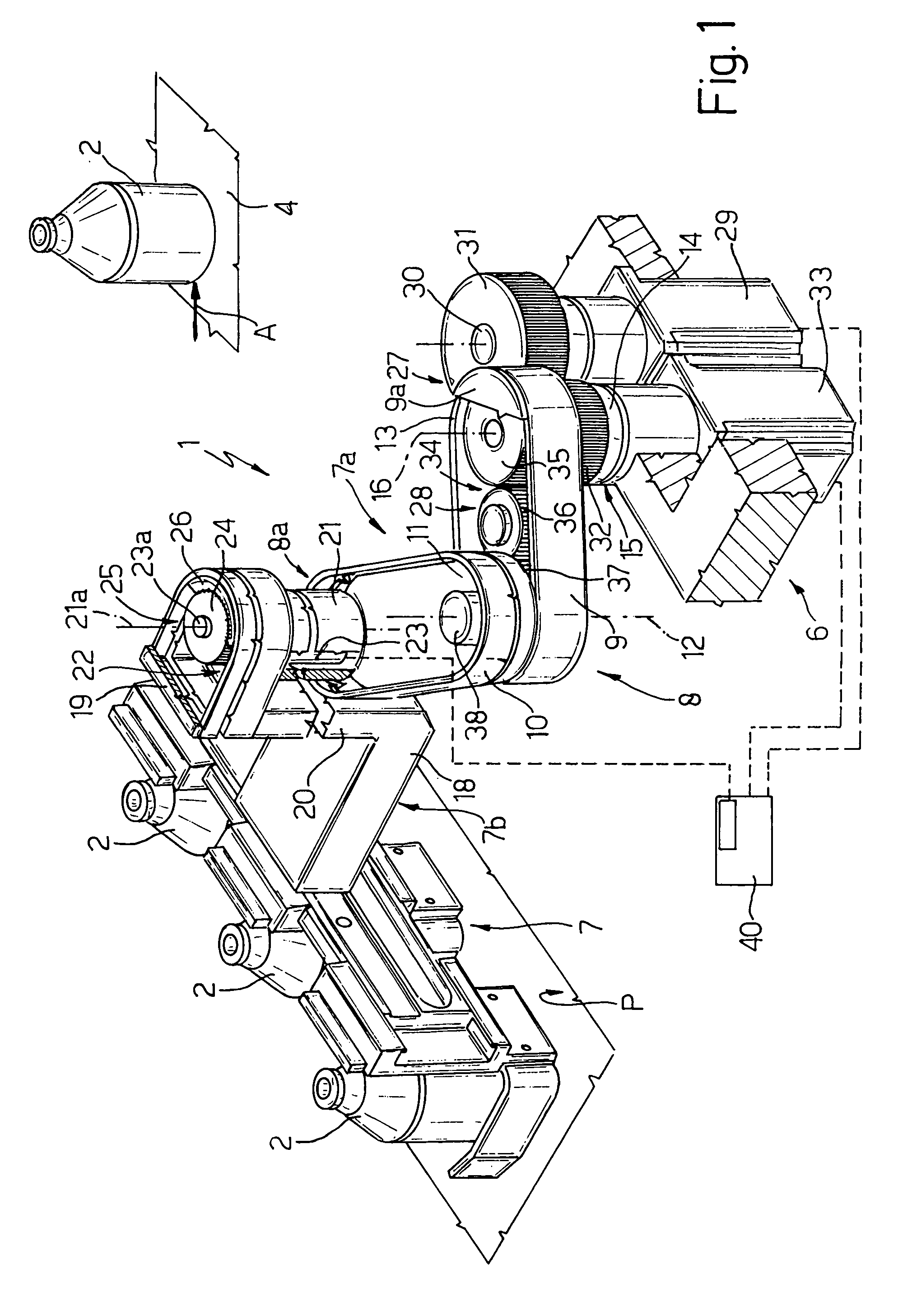
Figure 2 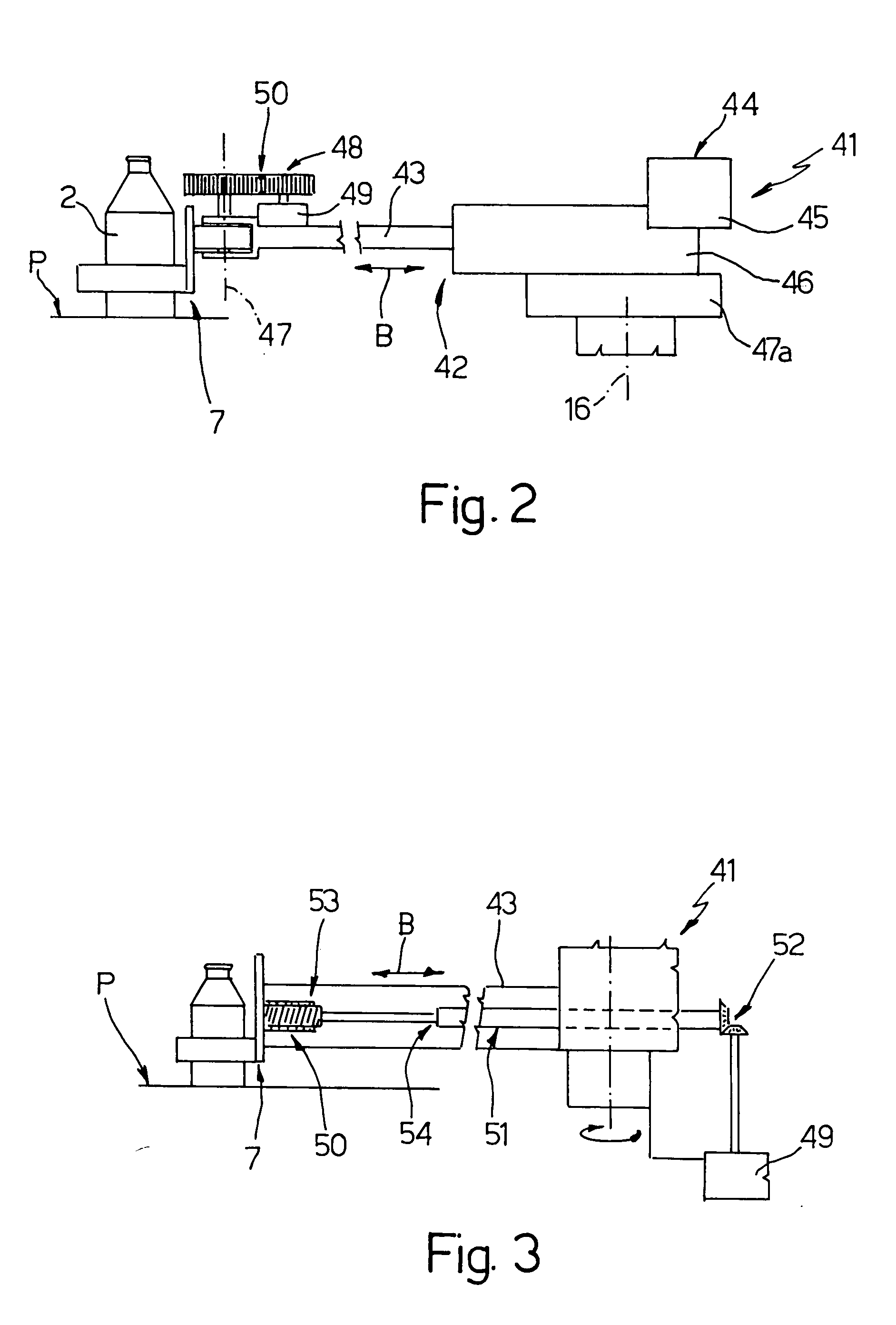
Figure 3
Abstract
Description
[0001] The present invention relates to a transfer unit for transferring glass articles. BACKGROUND OF THE INVENTION
[0002] As is known, hollow glass articles are formed in aligned, adjacent molds, and, once molded, are extracted from the respective molds and placed on a supporting surface, from which they are subsequently transferred onto a linear conveyor which feeds them successively to an output of the system.
[0003] The glass articles are transferred from the supporting surface to the linear conveyor by means of transfer units, each of which comprises a pickup member for engaging one or more articles to be transferred; a movable supporting arm fitted integrally with the pickup member; a pneumatic linear actuator for moving the supporting arm and the pickup member horizontally to and from the glass articles; and an angular actuator, normally electric, for rotating the supporting arm, about a fixed vertical hinge axis, between a pickup position, to pick the articles off the suppo...
Examples
Embodiment Construction
[0012] Number 1 in FIG. 1 indicates as a whole a transfer unit for transferring glass articles 2 from a fixed supporting surface P to a belt conveyor 4 (shown partly) for conveying articles 2 in a direction A to an output of the molding system (not shown) on which articles 2 are molded.
[0013] Transfer unit 1 comprises a fixed supporting frame 6 extending beneath supporting surface P; a known pickup and moving member 7 for engaging articles 2 for transfer; and an actuating device 7a for activating pickup member 7. Device 7a comprises a single articulated arm 8 interposed between pickup member 7 and frame 6, and in turn comprising only two hollow elongated portions 9 and 10. Portions 9 and 10 extend parallel to and over supporting surface P, and are connected to each other by a hinge 11 to rotate, with respect to each other, about a movable hinge axis 12 perpendicular to surface P. With reference to FIG. 1, portion 9 comprises an end portion 13, opposite the end portion hinged to por...