
Image display apparatus and head mount display
Patent Information
- Authority / Receiving Office
- US · United States
- Current Assignee / Owner
- Publication Date
- 2006-11-30
Smart Images
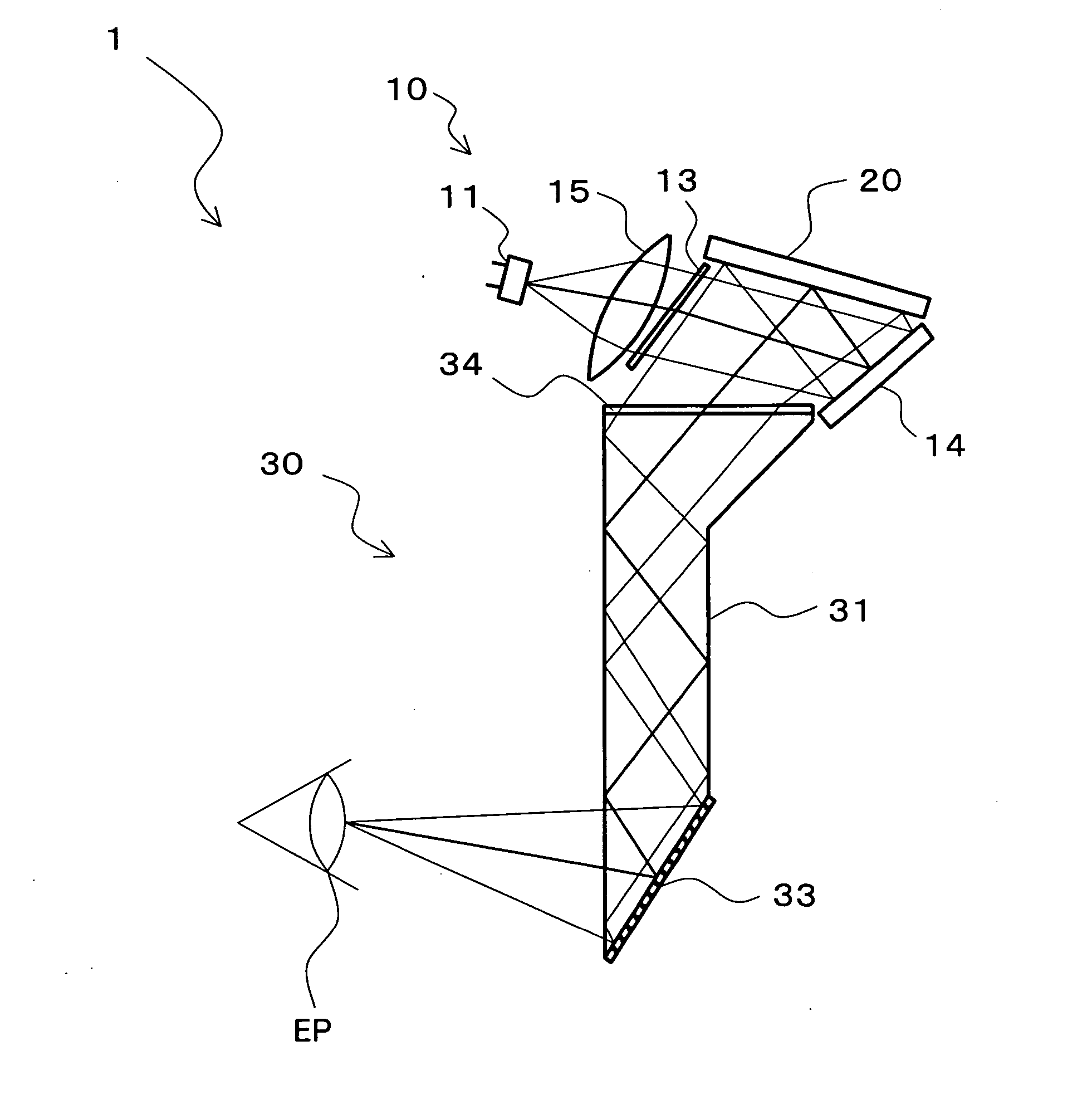
Figure 1 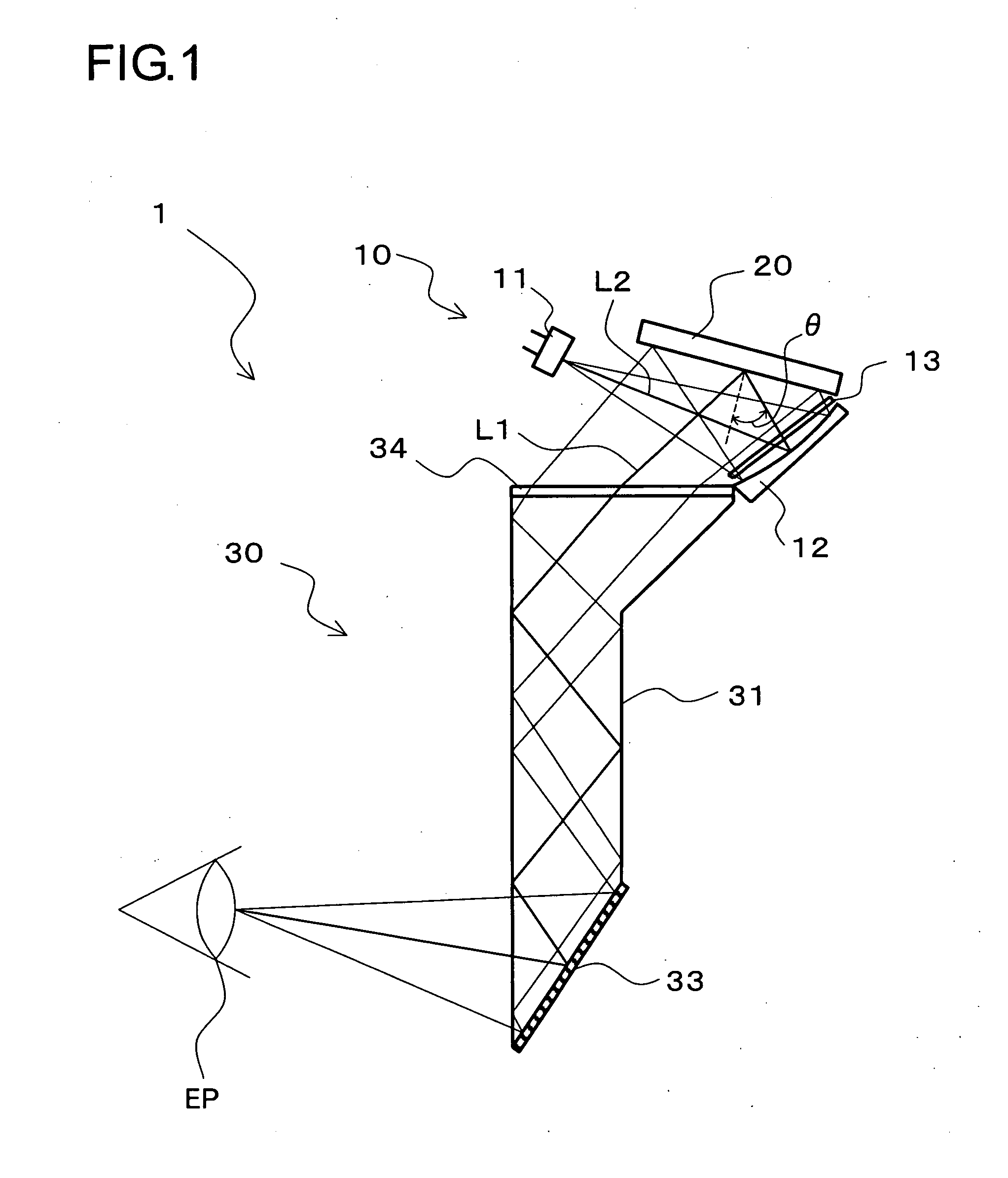
Figure 2 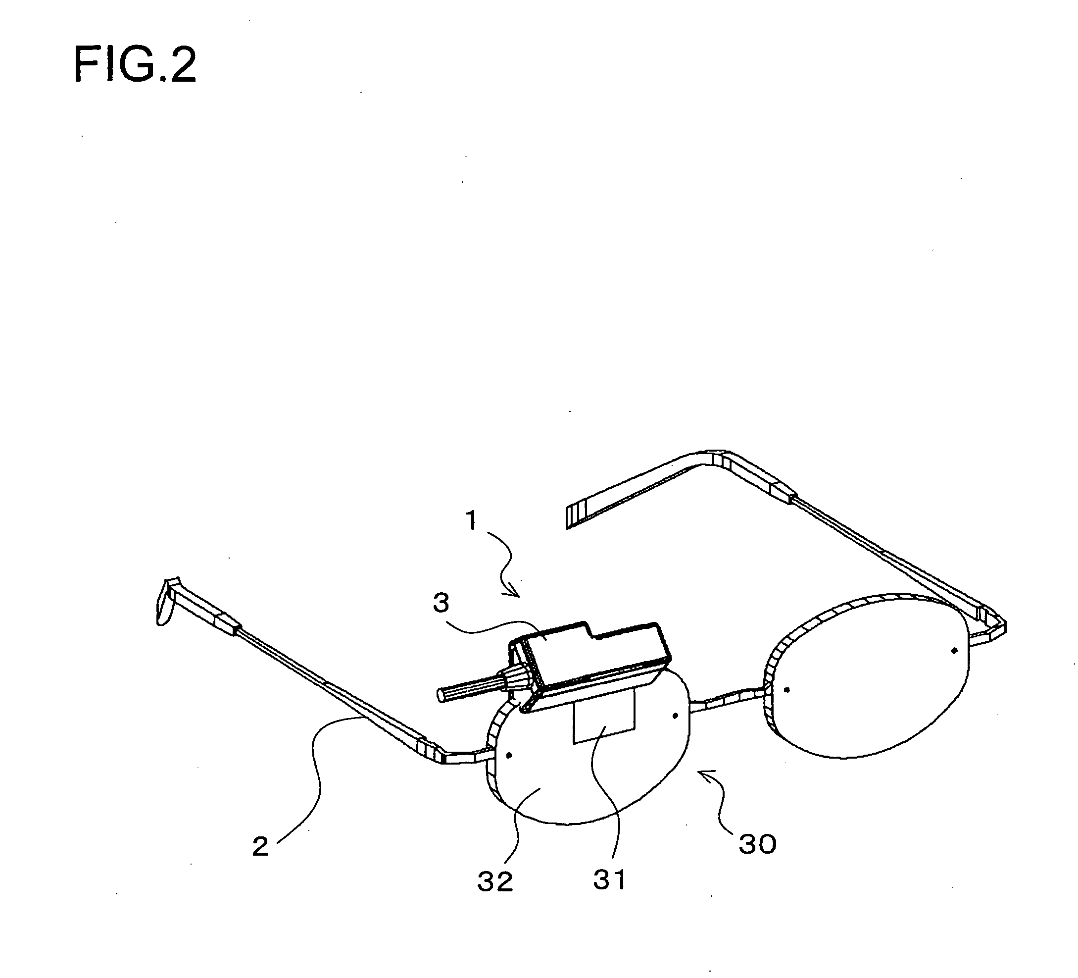
Figure 3
Abstract
Description
[0001] This application is based on the Japanese Unexamined Applications No. 2005-156906 filed on May 30, 2005, No. 2005-235626 filed on Aug. 16, 2005, and No. 2006-037932 filed on Feb. 15, 2006, of which the disclosures are hereby incorporated by reference. BACKGROUND OF THE INVENTION
[0002] 1. Field of the Invention
[0003] The present invention relates to an image display apparatus for projecting an image displayed on a display device (for example, a reflective display device) onto the eyes of a viewer as a virtual image, and to a head mounted display (hereinafter referred to as an HMD) equipped with the image display apparatus.
[0004] 2. Description of the Prior Art
[0005] An apparatus is known as a so-called HMD which is mounted on the head of a viewer for projecting the image, which has been produced by a display device, as a virtual image onto the pupil of the viewer across an eyepiece optical system. The display device employed in the HMD is classified into a transmissive typ...
Examples
embodiment 1
[0061] Embodiment 1 of the present invention will be described referring to the relevant drawings.
1. Arrangement of HMD
[0062]FIG. 2 is a perspective view schematically showing an arrangement of a head mount display (hereinafter referred to as an HMD) according to the present invention. The HMD includes an image display apparatus 1 and a supporting member 2 (supporting means) for supporting the image display apparatus 1 in front of eyes of a viewer.
[0063] The image display apparatus 1 is arranged for allowing the viewer to view background or external scene in a see-through manner, and at the same time providing an image of interest to be viewed as a virtual image by the viewer. The image display apparatus 1 includes an illumination optical system 10 (See FIG. 1) and a display device 20 (see FIG. 1) both installed in a housing 3 and an eyepiece optical system 30 assembled together with the housing 3. The eyepiece optical system 30 is arranged of substantially one of spectacles (th...
embodiment 2
[0164] Another embodiment of the present invention will be described referring to the relevant drawings. For ease of the description, like elements are denoted by like numerals as those of Embodiment 1 and will be explained in no more detail.
[0165]FIG. 12 is a cross sectional view schematically showing an arrangement of an image display apparatus 1 of this embodiment. In this embodiment, the eyepiece optical system 30 includes a free-surface prism 35 which replaces the eyepiece prism 31 in Embodiment 1.
[0166] The free-surface prism 35 has a first surface 35a thereof provided as the incident surface for receiving an image light from the display device 20, a second surface 35b thereof provided at the viewer pupil EP side for acting as the full reflection / transmission surface, and a third surface 35c thereof provided as the reflecting surface to face the second surface 35b. The three surfaces are arranged of an aspherical shape at non-rotating symmetry. The first surface 35a is arcua...
embodiment 3
[0172] A further embodiment of the present invention will be described referring to the relevant drawings. For ease of the description, like elements are denoted by like numerals as those of Embodiment 1 or 2 and will be explained in no more detail.
[0173]FIG. 13 is a cross sectional view schematically showing an arrangement of an image display apparatus 1 of this embodiment. In this embodiment, the illumination optical system 10 in Embodiment 1 further includes a diffuser plate 17.
[0174] The diffuser plate 17 is provided for diffusing the incident light received along the optical path bent by the concave mirror 12. When the B, G, and R emitters of the light source 11 are aligned along the long side of the display device 20, the diffuser plate 17 may be arranged in a one-way diffusion mode to diffuse the incident light along the direction of the long side. Alternatively, the diffuser plate 17 may has a surface thereof undulated or be implemented by a hologram optical element of vol...