
Luminescent device and method for manufacturing the same
a technology manufacturing methods, which is applied in the direction of photoelectric discharge tubes, electric discharge lamps, instruments, etc., can solve the problems of deterioration poor productivity low efficiency of light emitting diodes, etc., and achieves the effect of small size and simple construction
Patent Information
- Authority / Receiving Office
- US · United States
- Current Assignee / Owner
- Publication Date
- 2007-06-28
- Estimated Expiration
- Not applicable · inactive patent
Smart Images
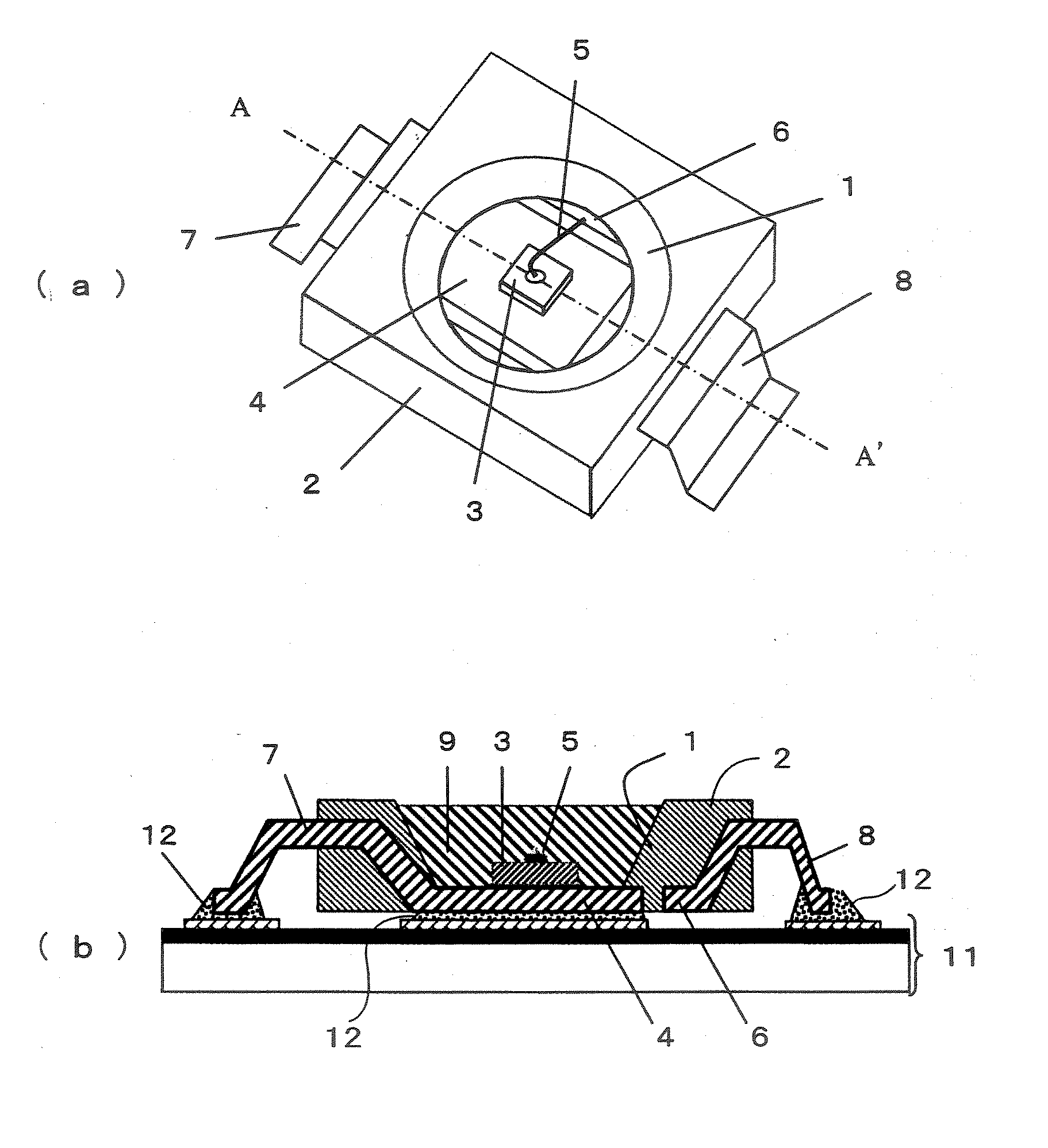
Figure 1 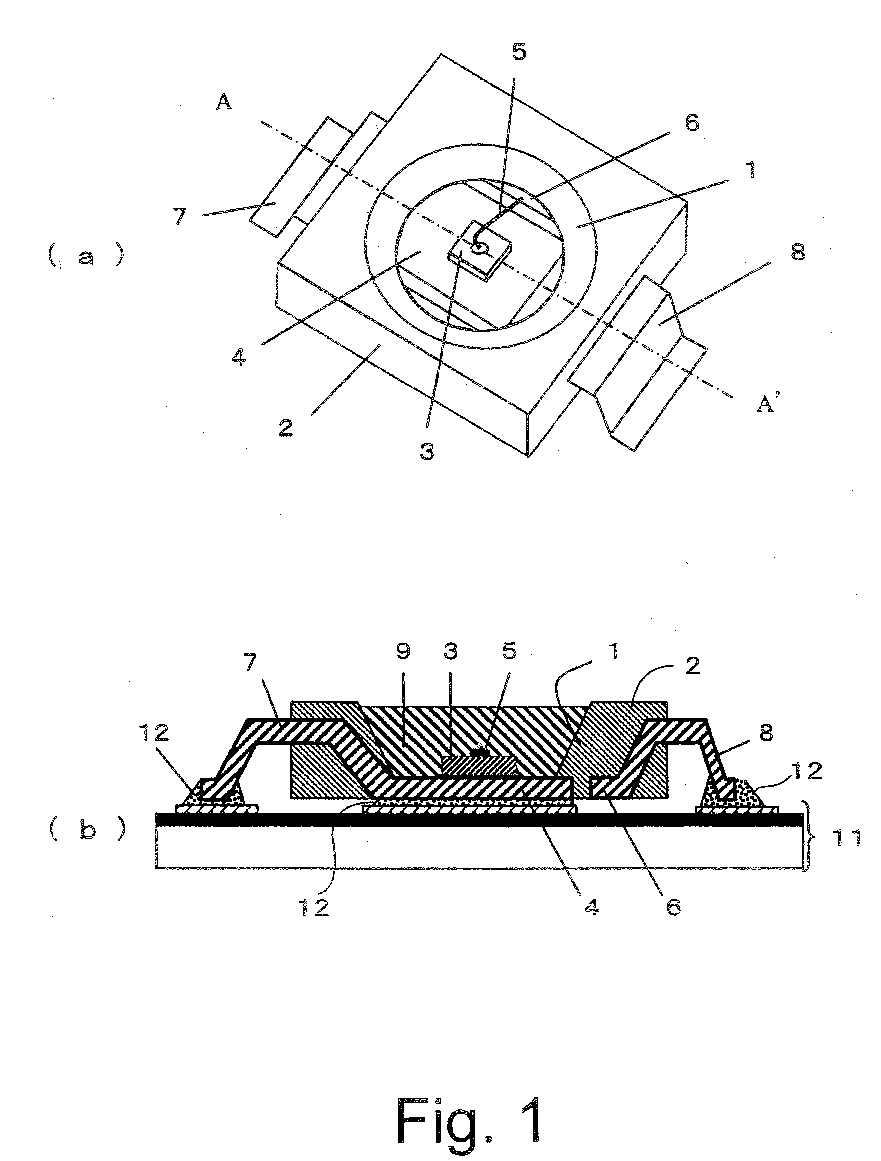
Figure 2 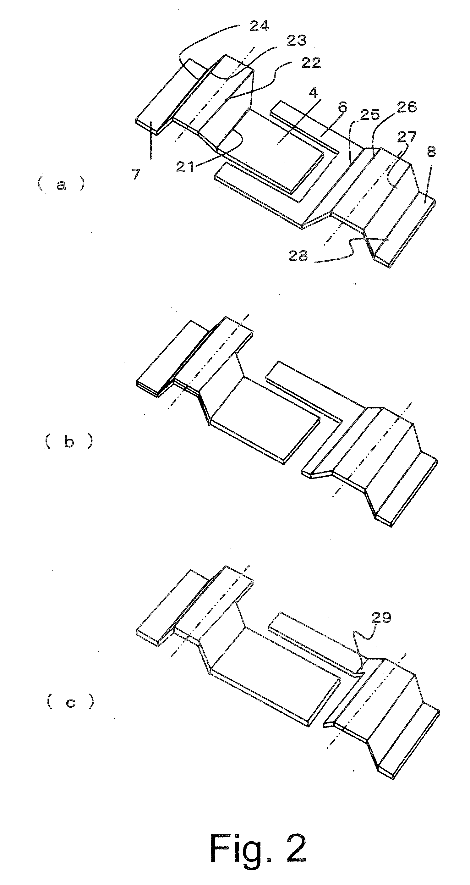
Figure 3
Abstract
Description
CROSS-REFERENCE TO RELATED APPLICATIONS
[0001] This application is based upon and claims the benefit of priority from the prior Japanese Patent Application No. 2005-376253, filed on Dec. 27, 2005; the entire contents of which are incorporated herein by reference. BACKGROUND OF THE INVENTION
[0002] 1. Field of the Invention
[0003] The present invention relates to a luminescent device and a method for manufacturing the same, and more particularly to a luminescent device composed of a light emitting diode having high heat radiation and a method for manufacturing the same.
[0004] 2. Description of the Background
[0005] In a conventional luminescent device, a pair of leads is combined by the transparent resin which was shaped by molding. At an end of an inner lead of a first lead, a light emitting diode is mounted, and an electrode of the light emitting diode and an end of an inner lead of a second lead are connected by a metal wire.
[0006] Outer leads of the first and second leads are b...
Examples
Embodiment Construction
[0023] Referring now to the drawings, wherein like reference numerals designate identical or corresponding parts throughout the several views, the embodiments of this invention will be described below.
[0024]FIG. 1(a) shows a perspective view of a luminescent device according to an embodiment of this invention, and FIG. 1(b) shows a sectional view of a line A-A′ of the luminescent device of the embodiment shown in FIG. 1(a).
[0025] The luminescent device shown in FIG. 1(a) is composed of a case 2 having an opening 1 in a conical shape, a light emitting diode chip 3 exposed on the bottom of opening 1 in the conical shape, an inner lead 4 on a die pad side for forming a die pad to which the light emitting diode chip 3 is mounted, a wire 5 extending from an electrode on the surface of light emitting diode chip 3, an inner lead 6 on a wire pad side for forming a wire pad to which the other end of wire 5 is connected, an outer lead 7 on the die pad side which is continued to inner lead 4...