
Method for forming an optical converter
a fiber optic and faceplate technology, applied in the direction of bundled fibre light guides, semiconductor devices, solid-state devices, etc., can solve the problems of increasing the overall requirements for using fiber optic faceplates as optical converters for electronic image display, increasing the complexity of tiling arrangements, and reducing the cost of fabrication. , the effect of easy fabrication
Patent Information
- Authority / Receiving Office
- US · United States
- Patent Type
- Applications(United States)
- Current Assignee / Owner
- Publication Date
- 2007-12-06
- Estimated Expiration
- Not applicable · inactive patent
Smart Images
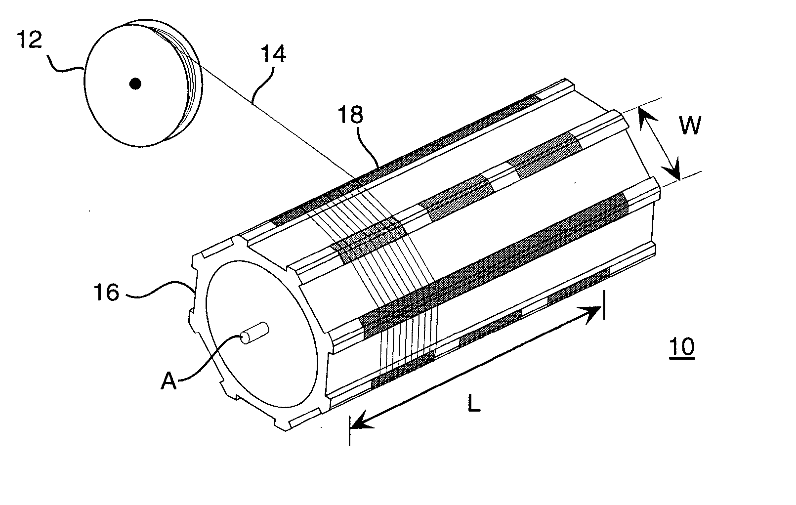
Figure 1 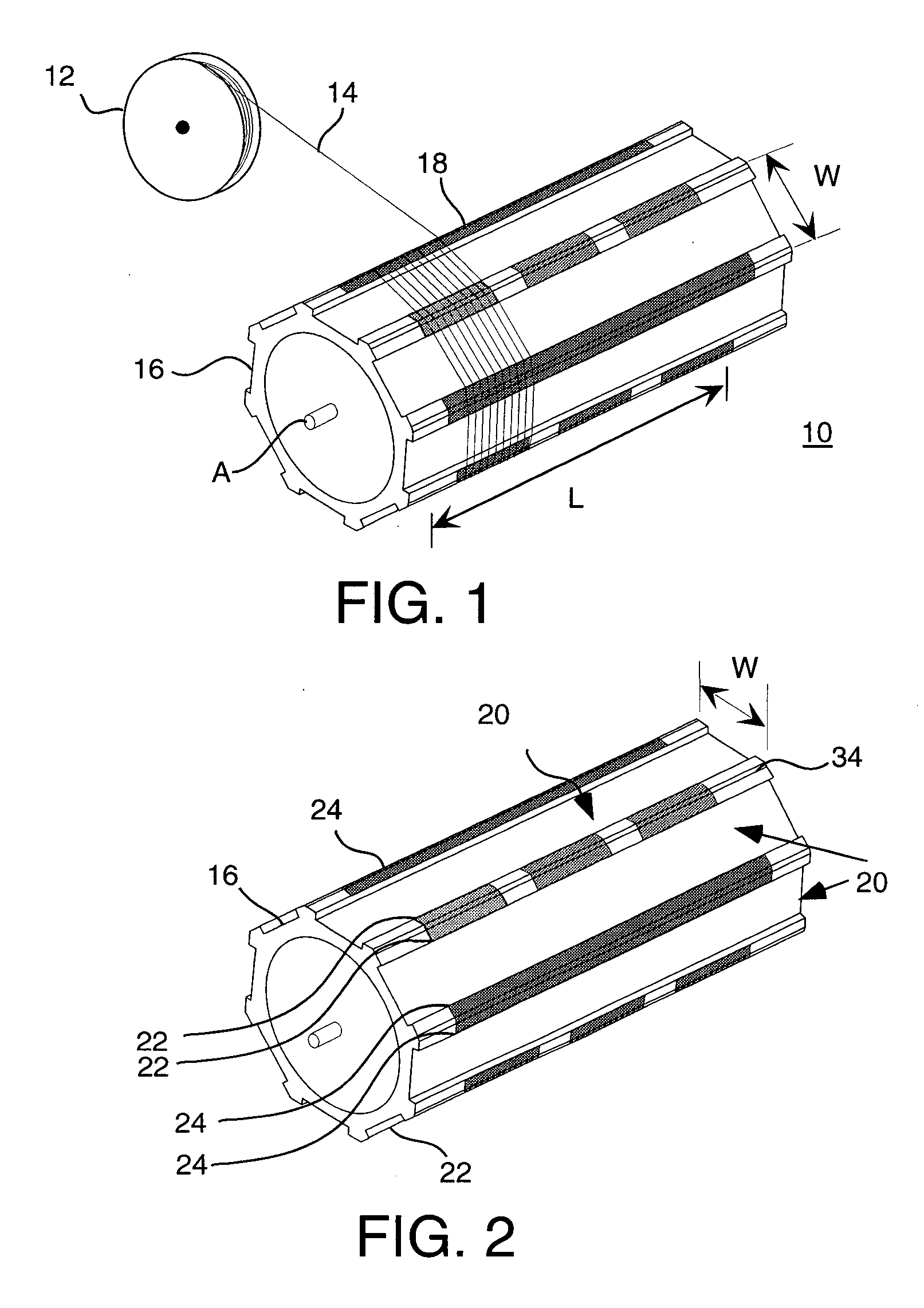
Figure 2 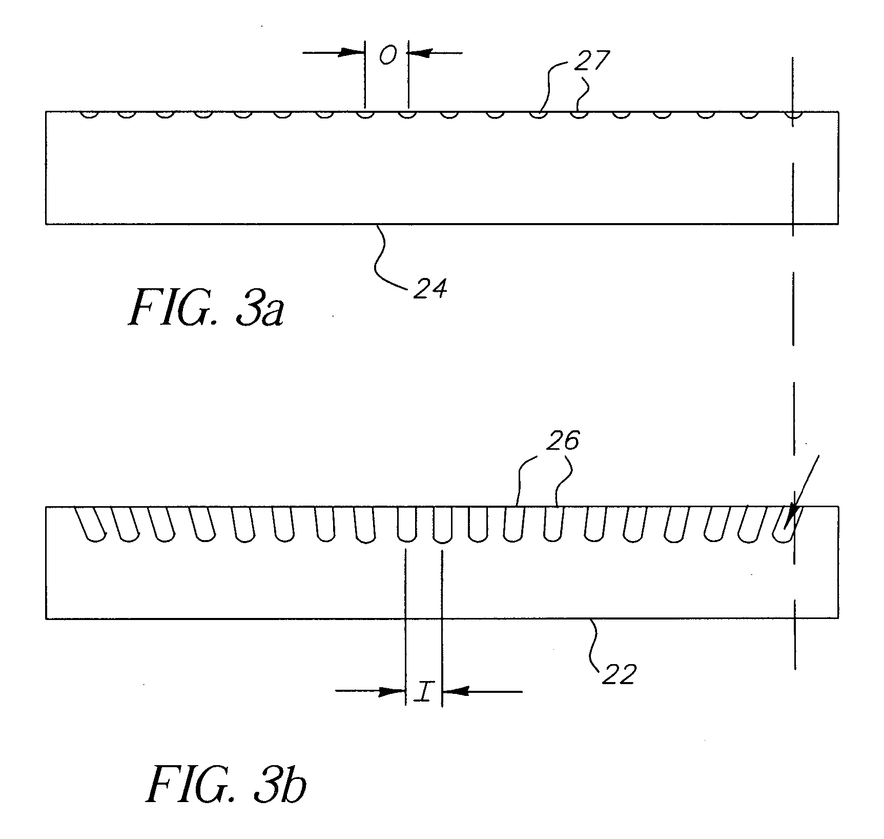
Figure 3
Abstract
Description
CROSS-REFERENCE TO RELATED APPLICATIONS
[0001] This is a divisional of U.S. application Ser. No. 10 / 314,843, entitled “Optical Converter Formed From Flexible Strips,” filed Dec. 9, 2002 by Roger S. Kerr, et al.FIELD OF THE INVENTION
[0002] This invention generally relates to fabrication of fiber optic faceplates as optical converters for use in imaging systems and more particularly relates to a fiber optic faceplate fabricated from flexible strips containing multiple light guides. BACKGROUND OF THE INVENTION
[0003] One advantage of electronic display systems is the capability to display an image in a variety of formats and sizes. There is particular interest in providing large scale displays, visible to thousands of viewers over considerable distance, such as would be useful for entertainment and advertising. One known method for providing large scale electronic displays is tiling, in which a matrix of smaller displays are linked together to form a larger display surface.
[0004] Ima...
Examples
Embodiment Construction
[0036] The present description is directed in particular to elements forming part of, or cooperating more directly with, apparatus in accordance with the invention. It is to be understood that elements not specifically shown or described may take various forms well known to those skilled in the art.
[0037] In order to understand the particular apparatus and methods applied using the present invention for fabricating fiber optic faceplates, it is most instructive to look first at the basic structural building block fabricated using the apparatus of the present invention and used for assembling the fiber optic faceplate. Referring to FIG. 12, there is shown a portion of a ribbon structure 40 which serves as a novel elemental component for fiber optic faceplate fabrication. Ribbon structure 40 comprises an array of optical fiber segments 50, generally disposed parallel to each other, for guiding light from an input edge 46, over width W, to an output edge 48. Fiber segments 50 on input...