
Airbag for a vehicle occupant restraint system
a technology for occupant restraints and airbags, which is applied in the direction of vehicle components, pedestrian/occupant safety arrangements, vehicular safety arrangments, etc., can solve the problem of airbags having to be deflated, and achieve the effect of preventing unplanned leakage flow and being easy to manufactur
Patent Information
- Authority / Receiving Office
- US · United States
- Patent Type
- Applications(United States)
- Current Assignee / Owner
- Publication Date
- 2008-01-10
- Estimated Expiration
- Not applicable · inactive patent
Smart Images
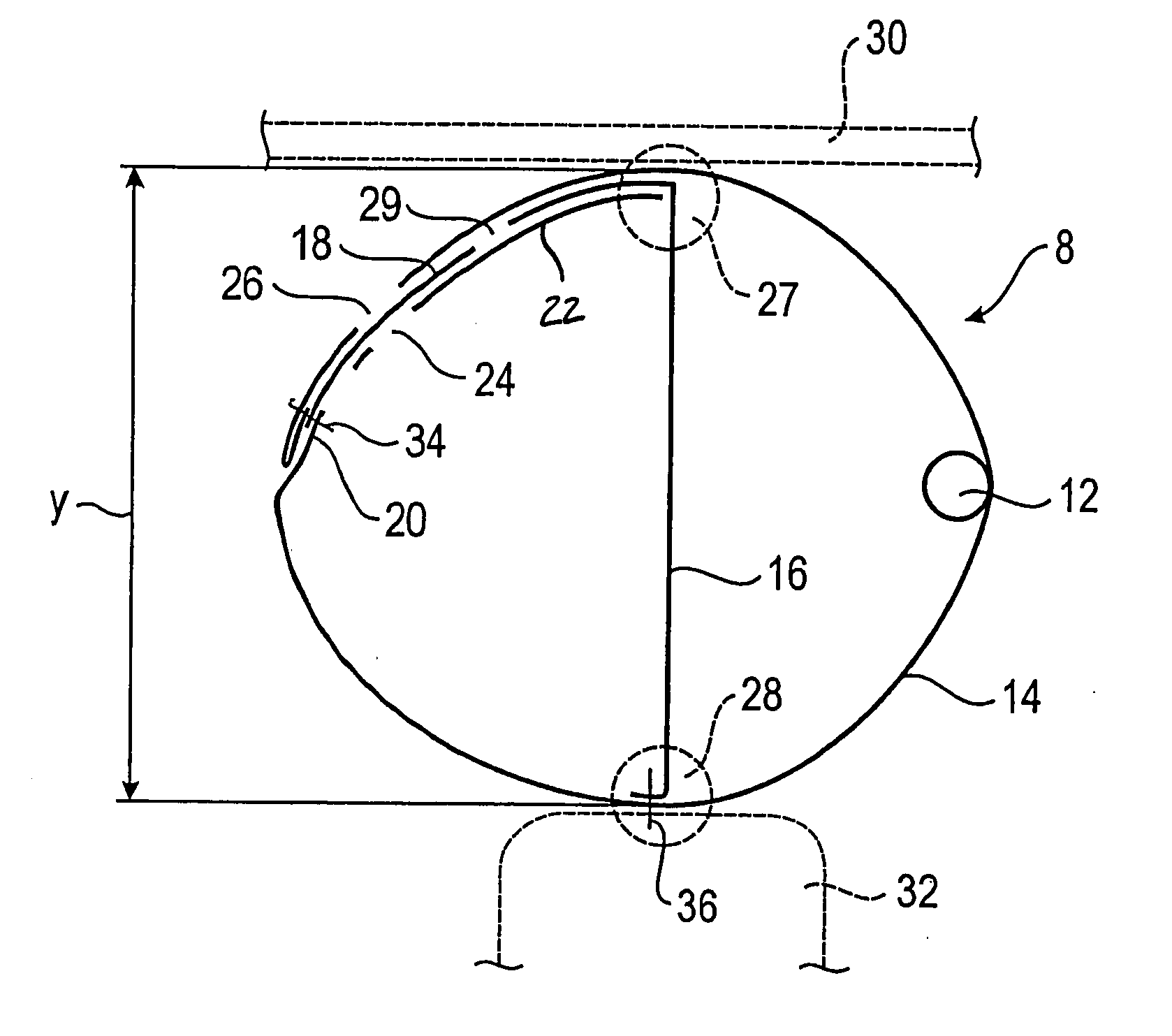
Figure 1 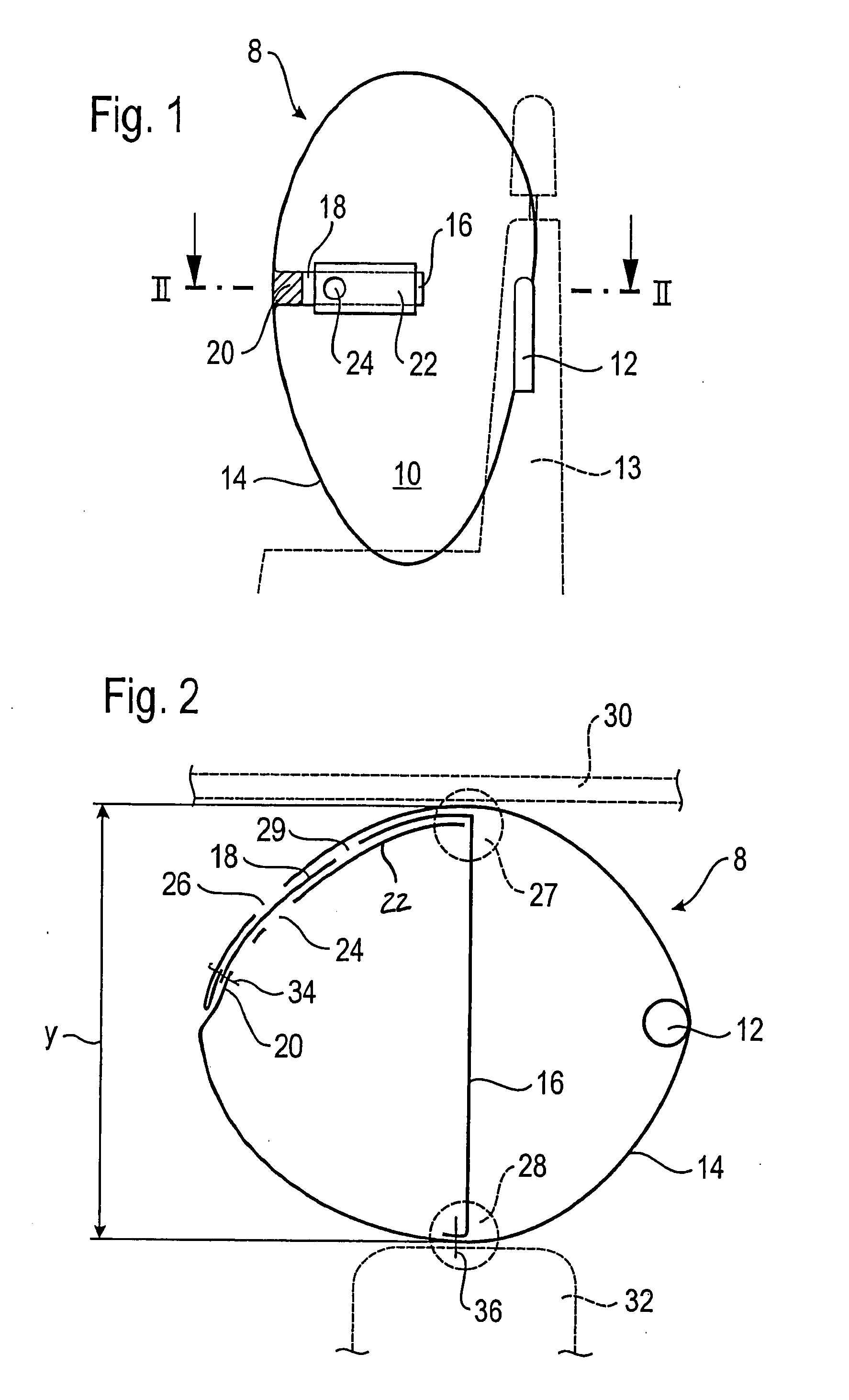
Figure 2 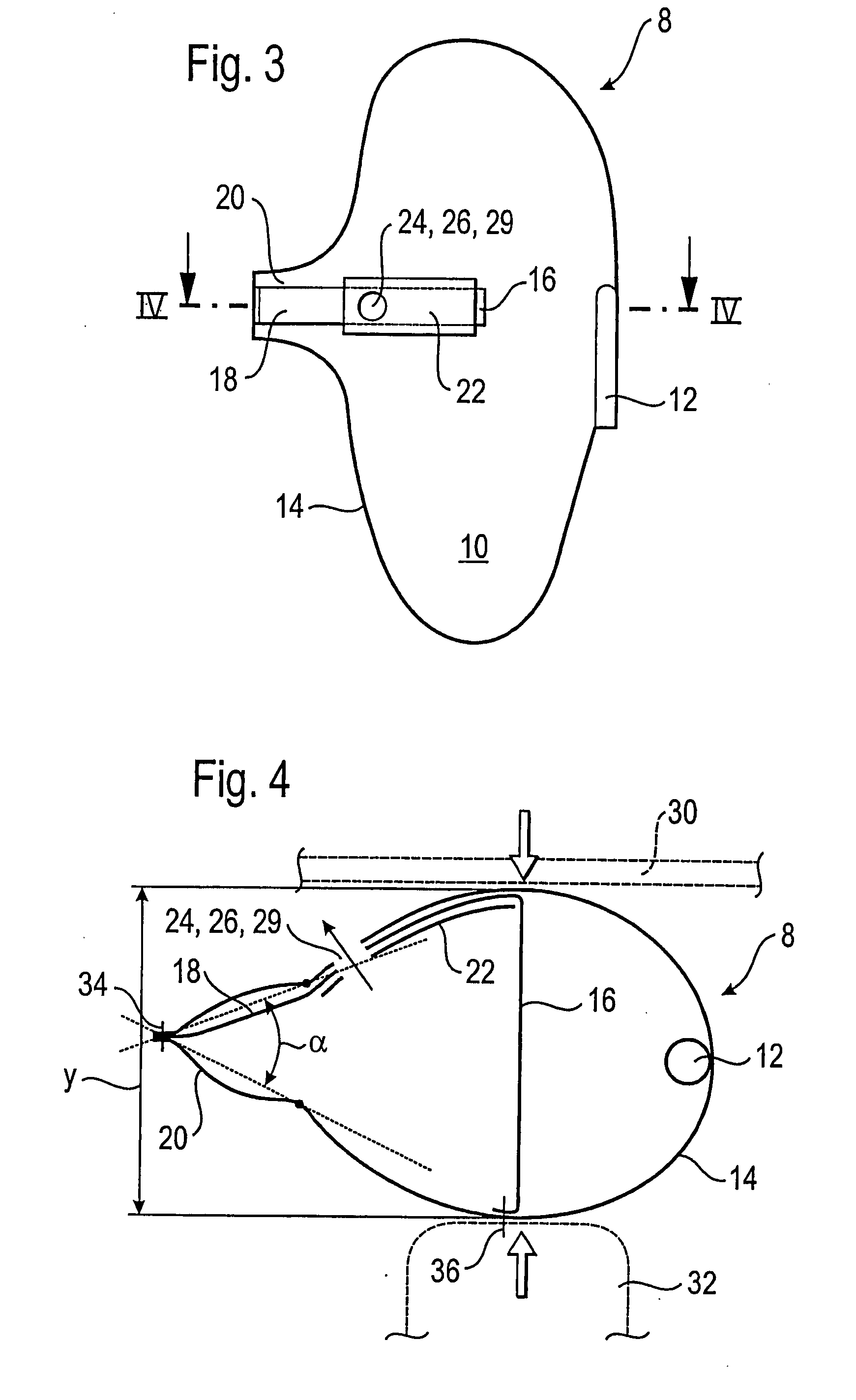
Figure 3
Abstract
Description
TECHNICAL FIELD
[0001] The invention relates to an airbag for a vehicle occupant restraint system, including an airbag wall having a gas outlet opening, and a control strap extending through an interior of the airbag along an airbag depth that is defined by a distance between two airbag wall areas that are situated opposite to each other and that are joined to one another by the control strap, a wall section being turned inside or outside relative to the inflated airbag, depending on the airbag depth.BACKGROUND OF THE INVENTION
[0002] Such an airbag has already been disclosed in the generic German patent application DE 102 36 859 A1 in which the wall section that can be turned inside or outside is a tube-like wall section that has a gas outlet opening. A first end of the control strap is fastened to the tube-like wall section near the gas outlet opening and a second, opposite end of the control strap is attached to the airbag wall. The length of the control strap and the attachment poin...
Examples
Embodiment Construction
[0021]By way of example, FIG. 1 shows an airbag module 8 with an airbag 10 according to the invention and a gas generator 12. On the basis of the shape and positioning of the gas generator 12, it is clear that the depicted module is a side-impact airbag module that is preferably integrated into the backrest of a vehicle seat 13, although the invention is not limited to such modules. The figure shows a schematic vertical section through the gas generator 12 and through an airbag wall 14 of the airbag 10. Moreover, a control strap 16 has been cut approximately in the middle of the airbag 10, this control strap 16 extending perpendicular to the plane of projection through the interior of the airbag along an airbag depth y (see FIG. 2). The control strap 16 is connected to a closure 18 that extends to the left on the inner surface of the airbag wall 14, as shown in FIG. 1, and that is attached to a wall section 20 being turned or folded towards the interior of the inflated airbag 10 and...