
PTC airflow heater
a technology of airflow heater and airflow outlet, which is applied in the field of heaters, can solve the problems of not having a heat controller function, easy to malfunction, and relatively short life of the warmer, and achieve the effect of minimizing the space of wiring connection, reducing the overall size of the housing, and minimizing the length of the electric wire usag
Patent Information
- Authority / Receiving Office
- US · United States
- Current Assignee / Owner
- Publication Date
- 2008-05-29
- Estimated Expiration
- Not applicable · inactive patent
Smart Images
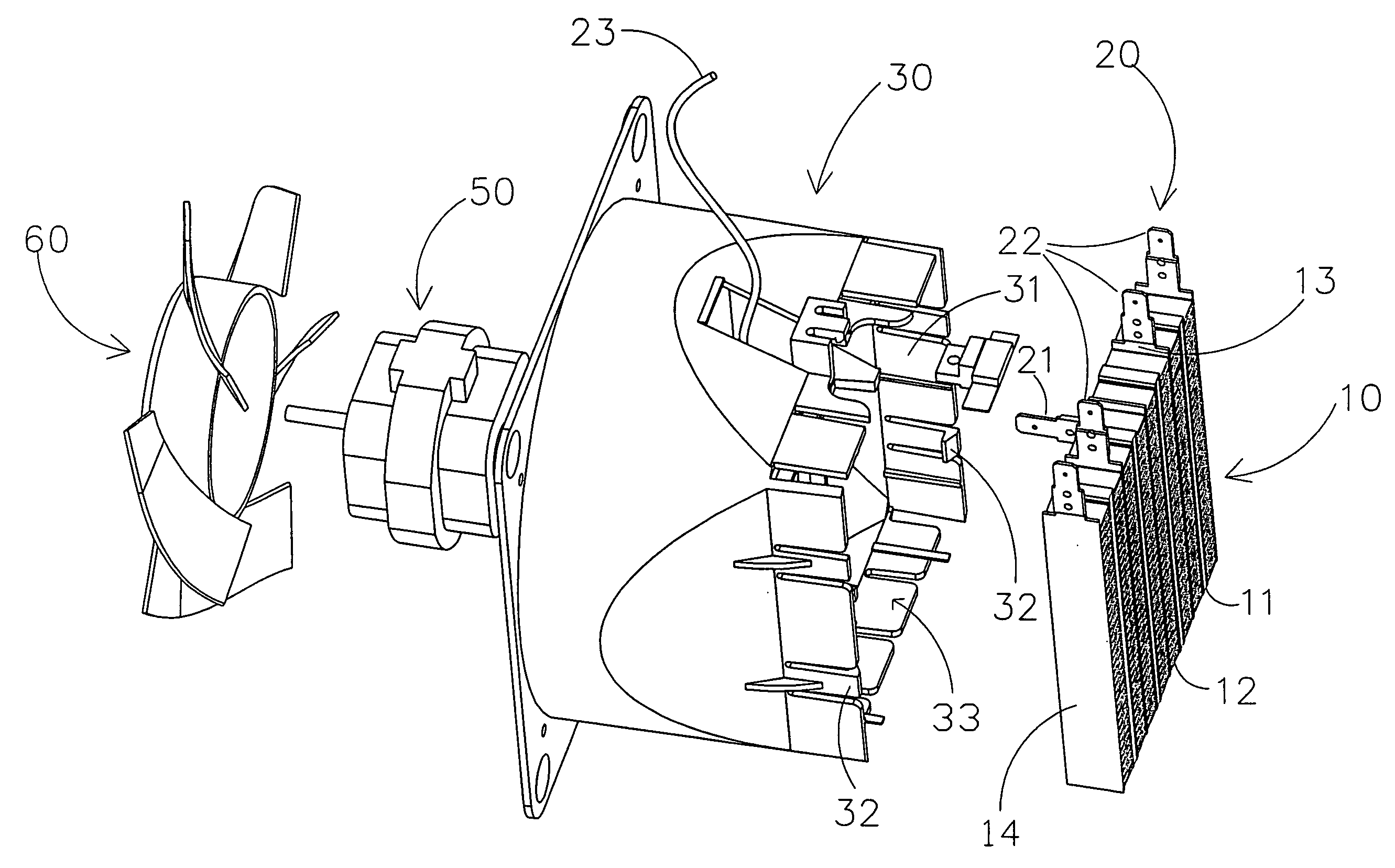
Figure 1 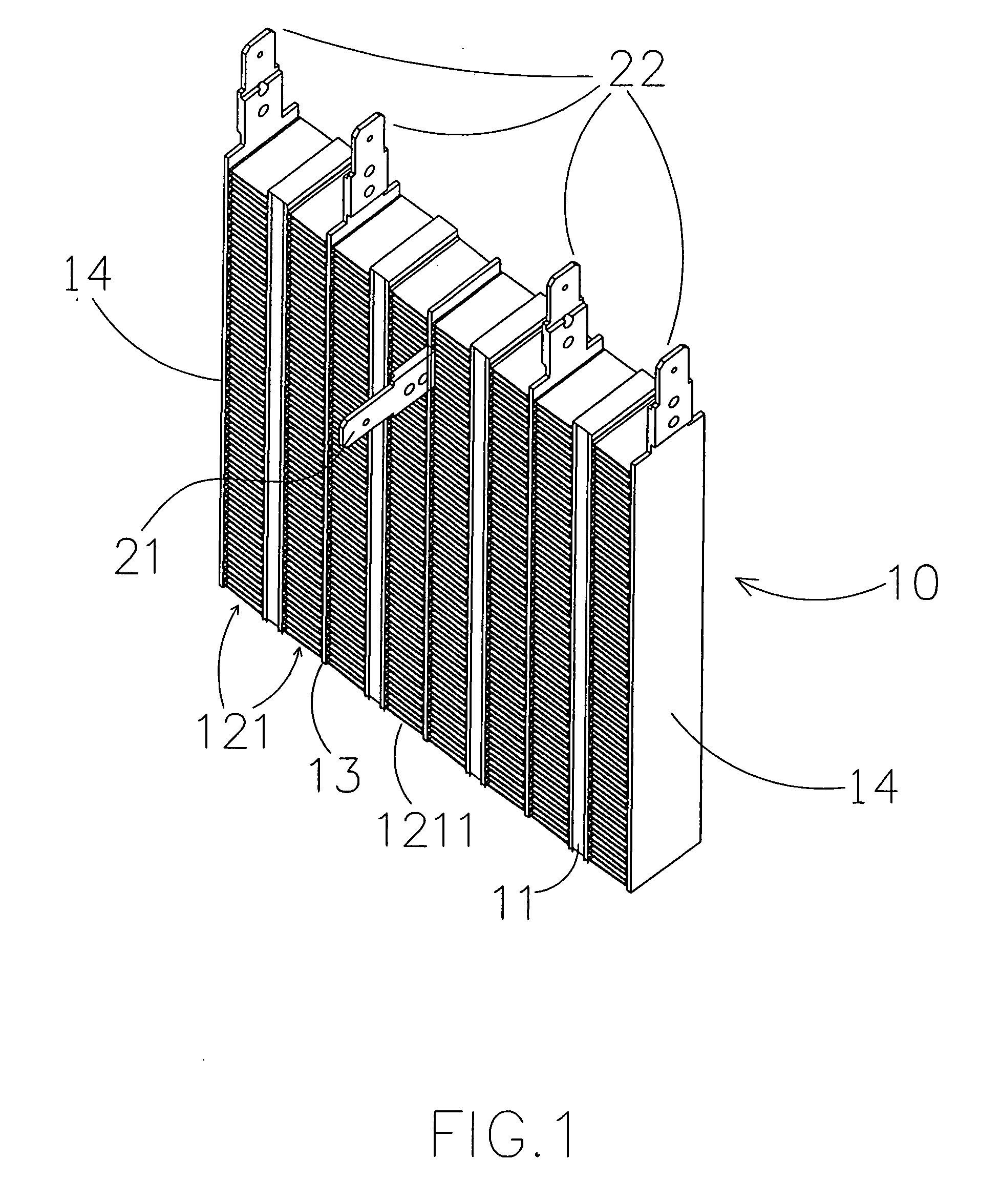
Figure 2 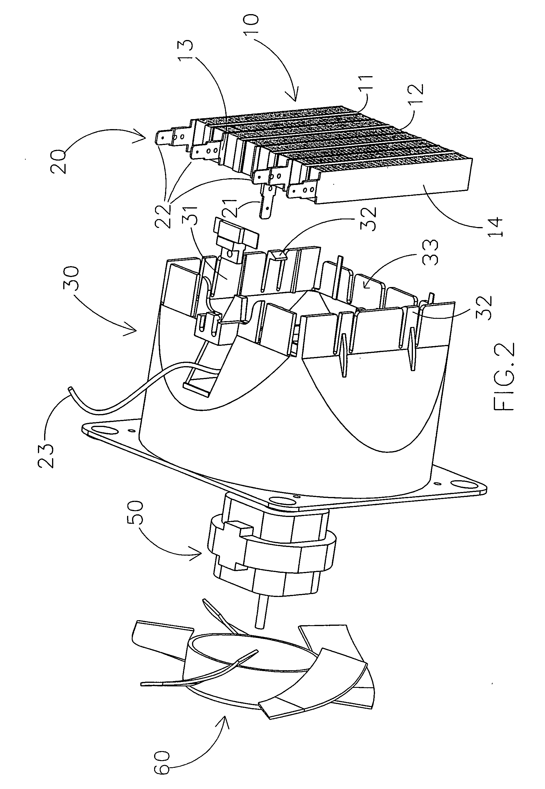
Figure 3
Abstract
Description
BACKGROUND OF THE PRESENT INVENTION
[0001] 1. Field of Invention
[0002] The present invention relates to a warmer, and more particularly to a heat airflow heater which uses an advance heat generating connector structure so as to reduce the overall material cost and to simplify the assembling configuration.
[0003] 2. Description of Related Arts
[0004] A conventional warmer, as a common house appliance, is adapted for generating a flow of heated air. Heated air is blown out to the environment such a room can be kept at a comfortable temperature. The warmer usually uses a heat generator as a heat source which is embodies as one of an electric wire having a predetermined resistance, a heat generating panel, and a heat generating tube for generating heat. Such a conventional warmer does not have a heat controller function. Therefore, the life span of the warmer is relatively short and it is easy to malfunction and is not safe to use. Another type of conventional warmer uses a PTC (Positive Tempe...
Examples
Embodiment Construction
[0024]Referring to FIGS. 1 to 7 of the drawings, a PTC airflow heater according to a preferred embodiment of the present invention is illustrated, wherein the PTC airflow heater comprises a housing 70, a PTC heat generator 10 received in the housing 70, a n air source supported in the housing 70 at a position behind the PTC heat generator 10 for generating a flow of air towards the PTC heat generator. The PTC airflow heater further comprises a control arrangement supported at an upper portion of the housing 70 to control the PTC heat generator 10.
[0025]As shown in FIG. 7, the housing 70 comprises a front casing 71 and a rear casing 72 mounted thereto to define a receiving cavity between the front and rear casings 71, 72.
[0026]The air source comprises a fan blade 60 and a motor 50 driving the fan blade 60 via an output shaft to rotate so as to generate a flow of air towards the PTC heat generator 10. The control arrangement comprises a control unit 80 electrically connected between a...