
Battery pack
Patent Information
- Authority / Receiving Office
- US · United States
- Current Assignee / Owner
- Publication Date
- 2009-04-09
- Estimated Expiration
- Not applicable · inactive patent
Smart Images
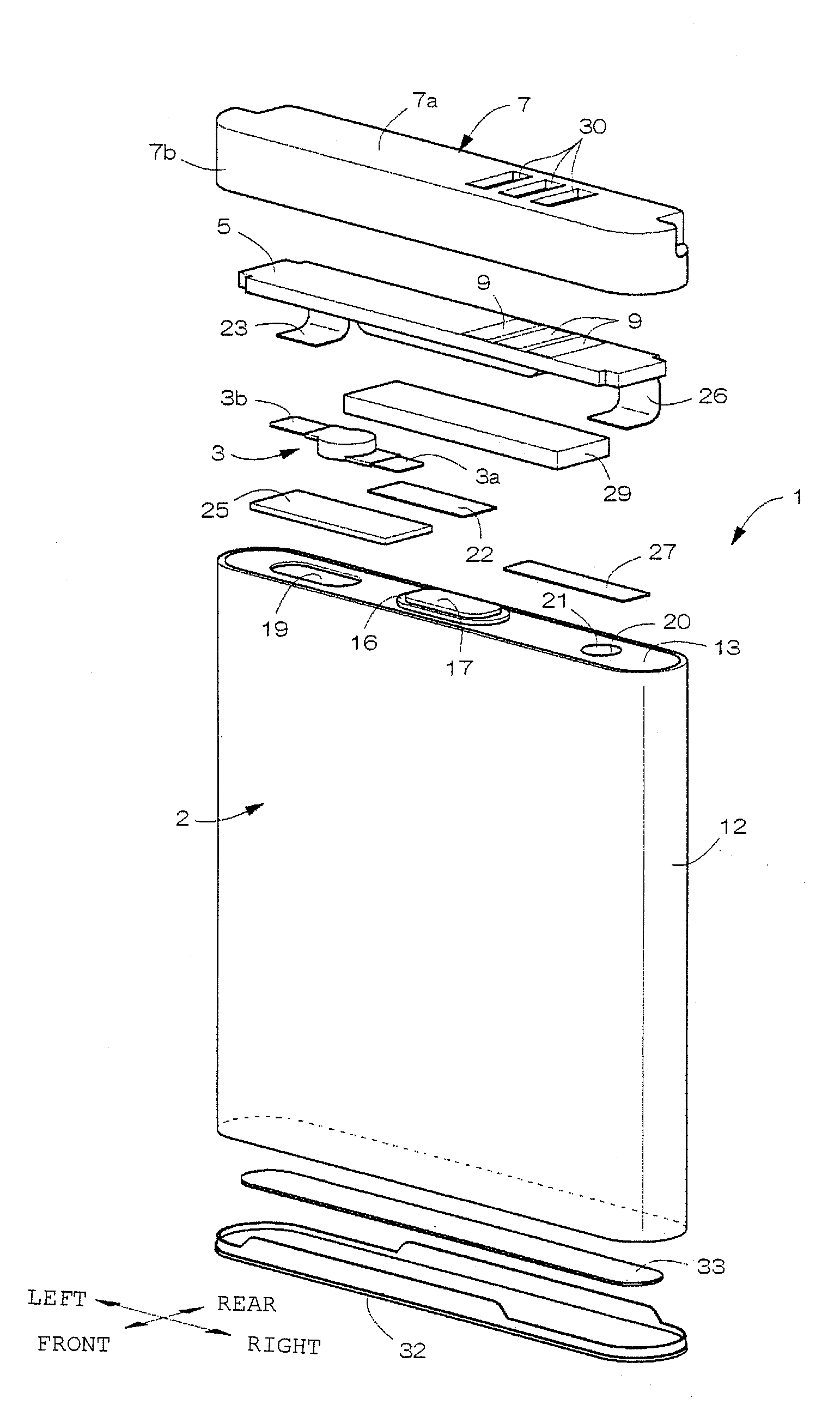
Figure 1 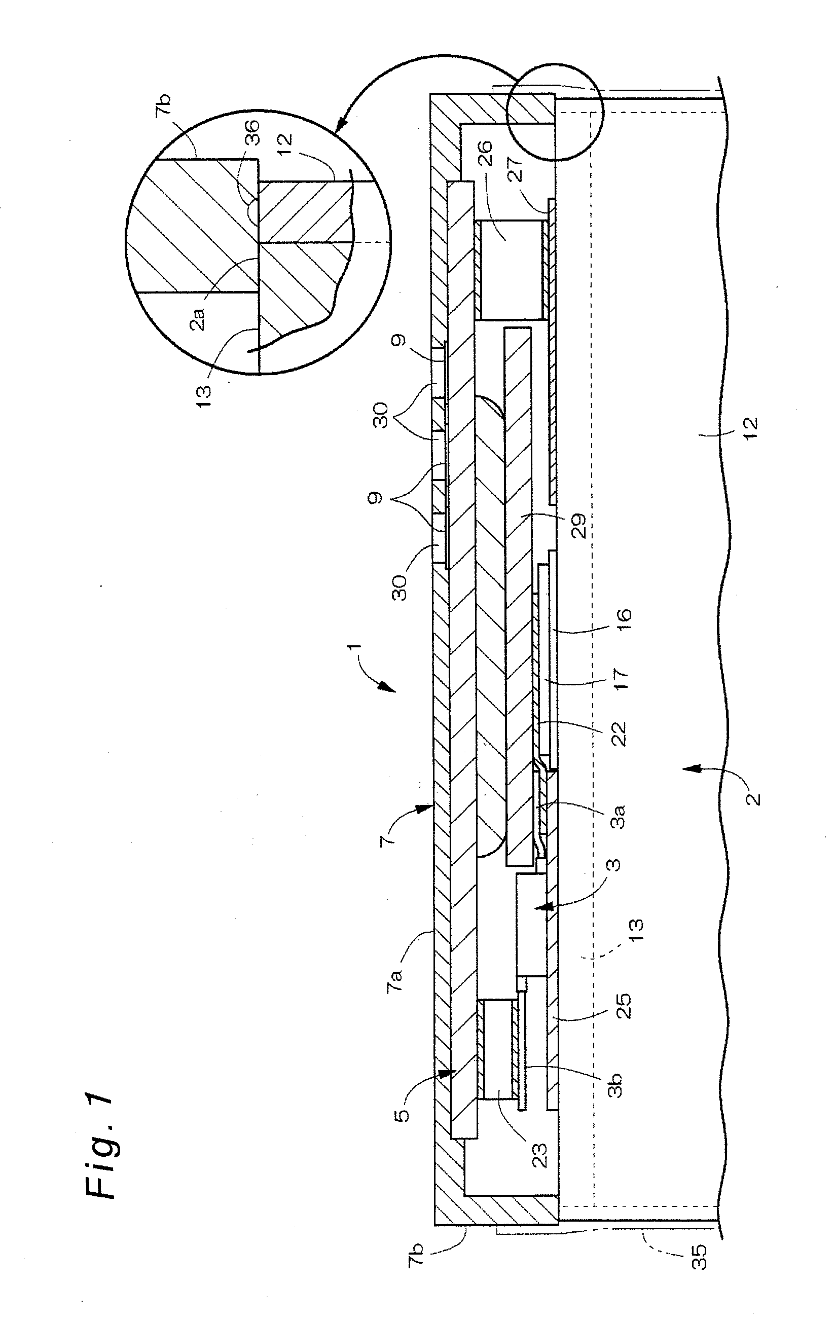
Figure 2 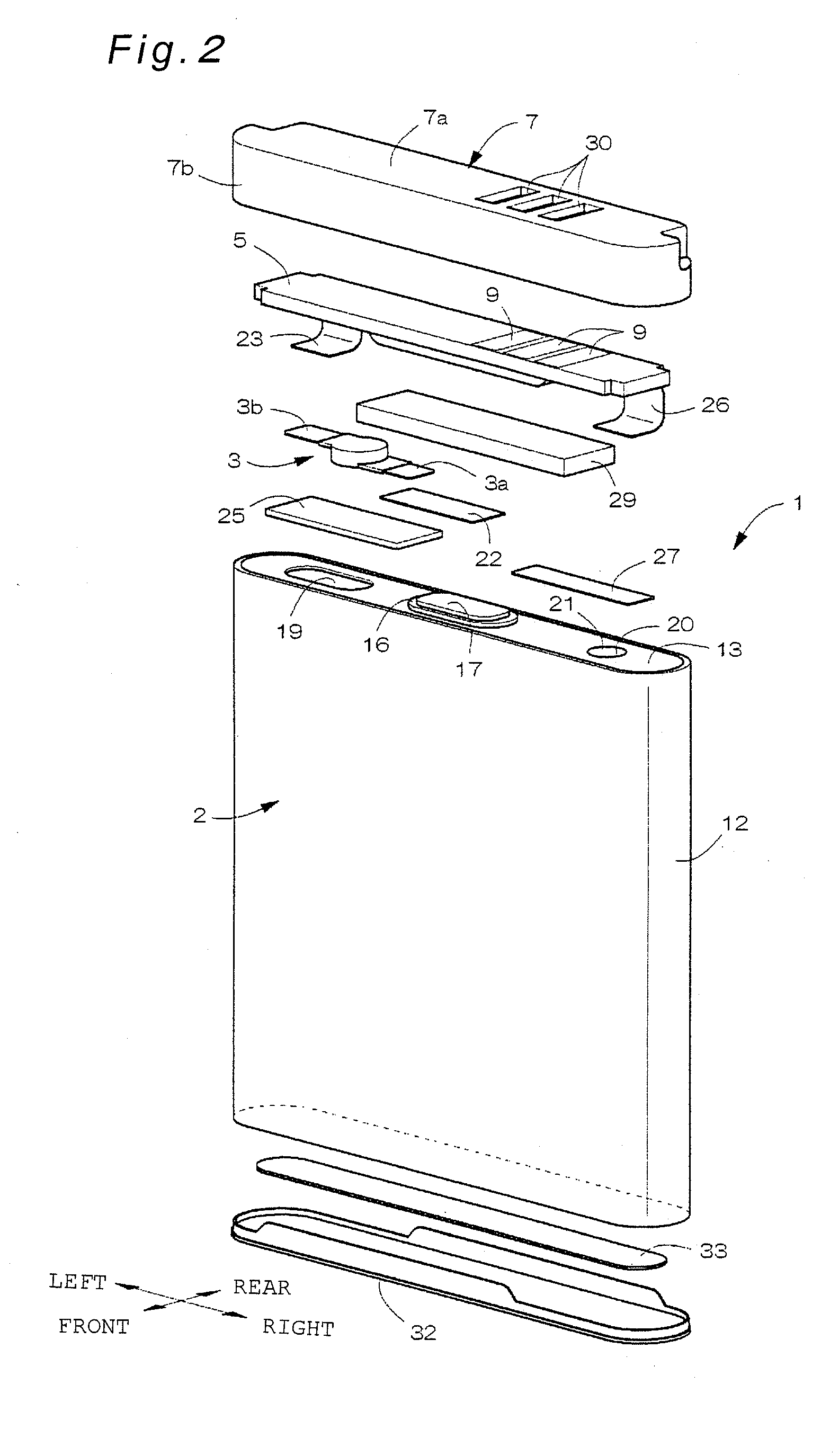
Figure 3
Abstract
Description
BACKGROUND OF THE INVENTION
[0001] 1. Field of the Invention
[0002] The present invention relates to a battery pack having a unit cell and a holder for holding a circuit board that is placed outside the unit cell.
[0003] 2. Description of Related Art
[0004] Conventionally, there have been known such battery packs of this type as disclosed in Documents 1 through 3, for instance. In the battery packs disclosed in Documents 1 through 3, a circuit board having a safety circuit and the like are placed outside a sealing plate of a flat-shaped unit cell and are covered with an exterior cover, which is then fixed to the unit cell, so that the exterior cover holding the circuit board and the like is integrated with the unit cell.
[0005] In the battery pack of Document 1, specifically, the integration is achieved by fixation of the circuit board and the exterior cover to the unit cell by resin molding. In the battery pack of Document 2, fitting projections are provided on a board holder held between th...
Examples
first embodiment
[0101]FIGS. 1 through 5 show a first embodiment of a battery pack according to the invention. As shown in FIGS. 1 through 3, a battery pack 1 has a unit cell 2 including a battery case (outer can) 12 having an upper face opening and made of metal and including a sealing plate 13 closing the upper face opening of the battery case 12 and made of metal, a protection element 3 placed above the sealing plate 13, a circuit board 5 placed above the sealing plate 13, and an exterior cover 7 covering the protection element 3 and the circuit board 5 and made of synthetic resin. The protection element 3 is a thermal fuse (PTC) or the like, for instance. Battery packs of the first through fifth embodiments present examples in which a holding member for holding the circuit board is the exterior cover.
[0102]Specifically, the unit cell 2 is a secondary cell such as lithium ion battery that allows discharge and charge thereof and, as shown in FIG. 2, is formed in shape of a flat rectangular paralle...
second embodiment
[0116]FIGS. 6 and 7 show a second embodiment of a battery pack according to the invention. The second embodiment is different from the first embodiment in that a YAG laser beam 31 is applied with utilization of recessed thin wall parts formed partially on outer periphery of a lower end (opening edge) of a peripheral side wall 7b of an exterior cover 7.
[0117]As shown in FIGS. 6 and 7, a plurality of recesses 38 placed circumferentially are formed on the outer periphery of the lower end of the peripheral side wall 7b of the exterior cover 7, and the thin wall parts 39 are formed between lower surfaces of inner periphery, in the drawing, of the recesses 38 and the lower end face of the peripheral side wall 7b of the exterior cover 7. In the thin wall parts 39, top surfaces thereof in the drawing (i.e., the lower surfaces of inner periphery, in the drawing, of the recesses 38) are formed as flat parts (flat surfaces) 39a placed generally in parallel with a top face 2a of a unit cell 2. ...
third embodiment
[0122]FIGS. 8 and 9 show a third embodiment of a battery pack according to the invention. In the third embodiment, a flange 40 protruding horizontally outward in the drawings is formed on outer periphery of a lower end of a peripheral side wall 7b of an exterior cover 7. In the flange 40, as shown in FIG. 9, a base end 40a of protrusion from the peripheral side wall 7b of the exterior cover 7 is positioned closer to inside of the exterior cover 7 than a reference surface 7c defined by an external shape of a top wall 7a of the exterior cover 7. Specifically, thicknesses of the peripheral side wall 7b are made the smaller at the lower position in the drawing, and thus an outer wall surface of the peripheral side wall 7b is made a slant surface that is positioned the closer to inside of the exterior cover 7 at the lower position in the drawing.
[0123]In the flange 40, a top surface (flat surface) thereof in the drawing that continues from the outer surface of the peripheral side wall 7b...