
Lever connector
a technology of lever connector and lever body, which is applied in the direction of coupling device connection, coupling parts engagement/disengagement, incorrect coupling prevention, etc., can solve the problems of restricted engagement of the second housing in the inclined posture into the inside of the hood, and the inclined second housing will break or damage the tab, etc., and achieve excellent space efficiency
Patent Information
- Authority / Receiving Office
- US · United States
- Patent Type
- Applications(United States)
- Current Assignee / Owner
- Publication Date
- 2011-06-16
- Estimated Expiration
- Not applicable · inactive patent
Smart Images
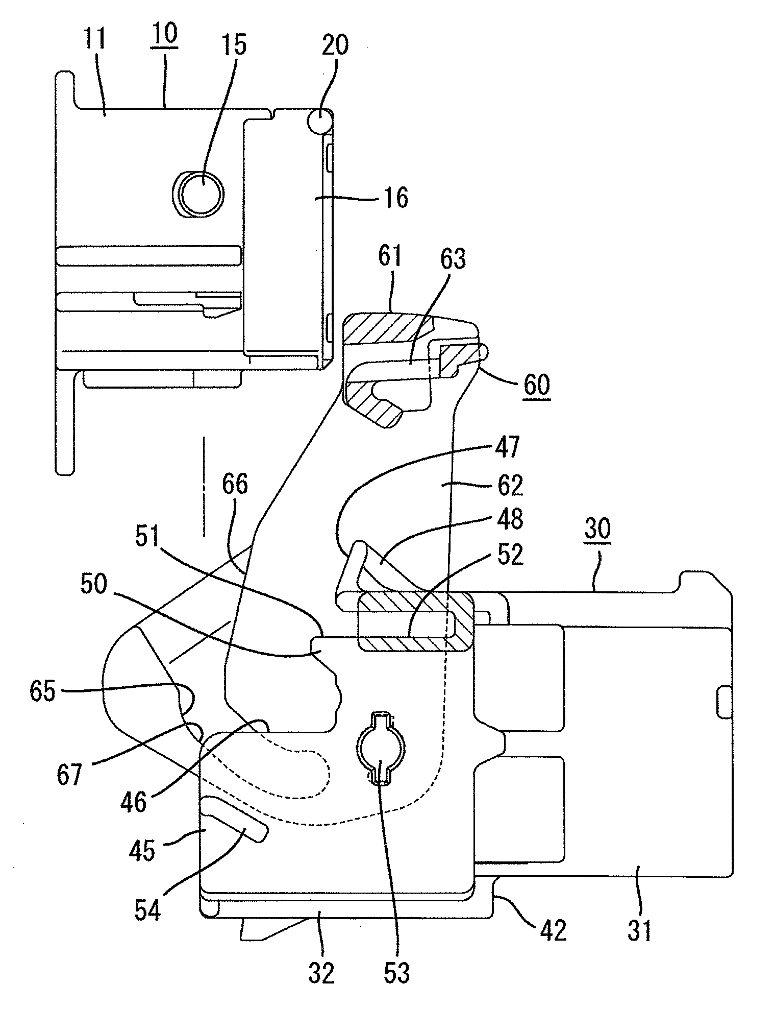
Figure 1 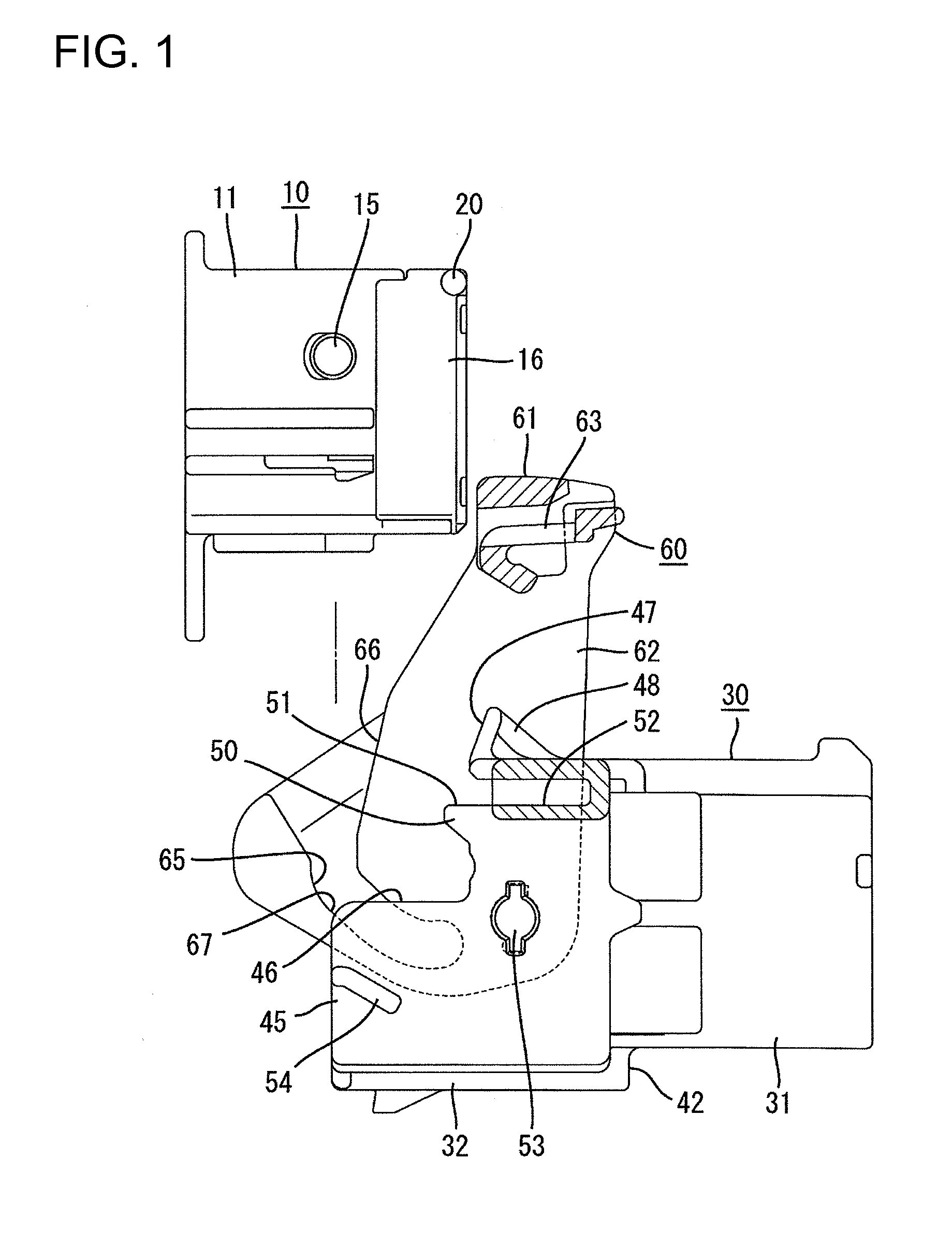
Figure 2 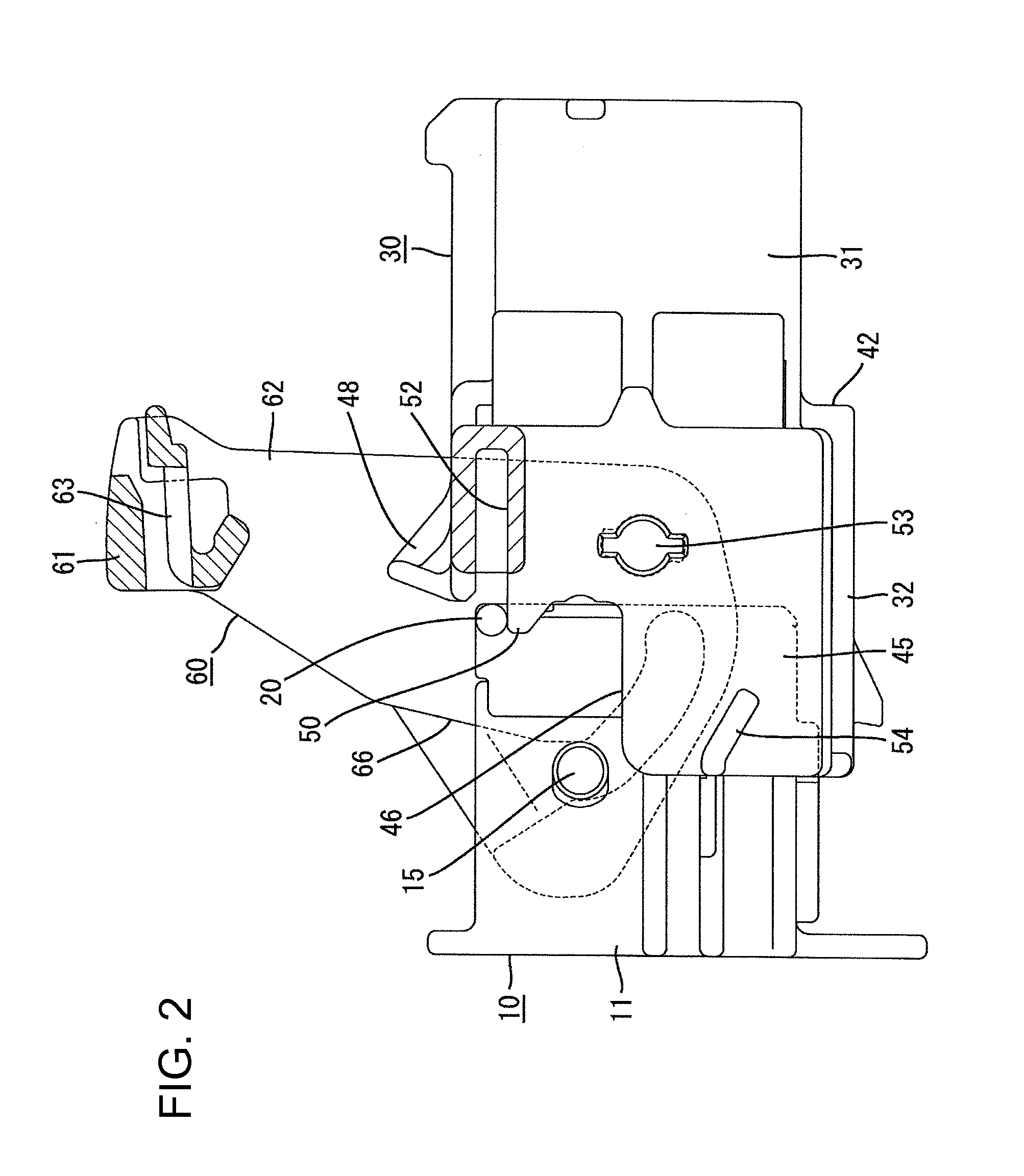
Figure 3
Abstract
Description
BACKGROUND OF THE INVENTION
[0001] 1. Field of the Invention
[0002] The invention relates to a lever connector.
[0003] 2. Description of the Related Art
[0004] JP-A-2008-27787 discloses a conventional lever connector with first and second housings that are engageable with each other. A lever is mounted on the first housing for rotation between an initial position and a fitting position. A cam groove is formed on the lever, and a cam follower projects from the second housing. The first and second housings are engaged slightly while holding the lever at the initial position. Thus, the cam follower is introduced into the cam groove. The lever then is rotated toward the fitting position. As a result, the cam follower is moved slidably on a surface of the cam groove so that a cam action is exerted between the lever and the second housing. Accordingly, it is possible to bring the first and second housings into the fitting engagement with a low manipulation force.
[0005] In the above-mentioned conve...
Examples
Embodiment Construction
[0024]A connector according to the invention has a male connector and a female connector that are engageable with each other. The female connector has a female housing 10 and the male connector has a male housing 30 and a lever 60. Ends of the connectors that are engaged with each other are referred to as the front ends herein.
[0025]The female housing 10 is made of a synthetic resin, and includes a quadrangular-block-shaped female housing body 11, as shown in FIG. 9. Cavities 12 extend longitudinally through the female housing body 11 and a deflectable lance 13 projects forwardly in each cavity 12. A deflection space 14 is formed below each lance 13 and opens at a front surface of the female housing body 11. As shown in FIG. 6, a female terminal fitting 80 is inserted into the inside of each cavity 12 from the rear and the lance 13 prevents removal of the properly inserted female terminal fitting 80.
[0026]The female terminal fitting 80 is formed by bending or otherwise forming a uni...