
Connector
a technology of connecting parts and connectors, applied in the direction of coupling device connection, securing/insulating coupling contact members, electrical devices, etc., can solve the problem that the terminal fitting cannot rotate into a position, and achieve the effect of easy engagement of the erroneous insertion prevention part and easy formation
Patent Information
- Authority / Receiving Office
- US · United States
- Patent Type
- Applications(United States)
- Current Assignee / Owner
- Publication Date
- 2012-06-14
Smart Images
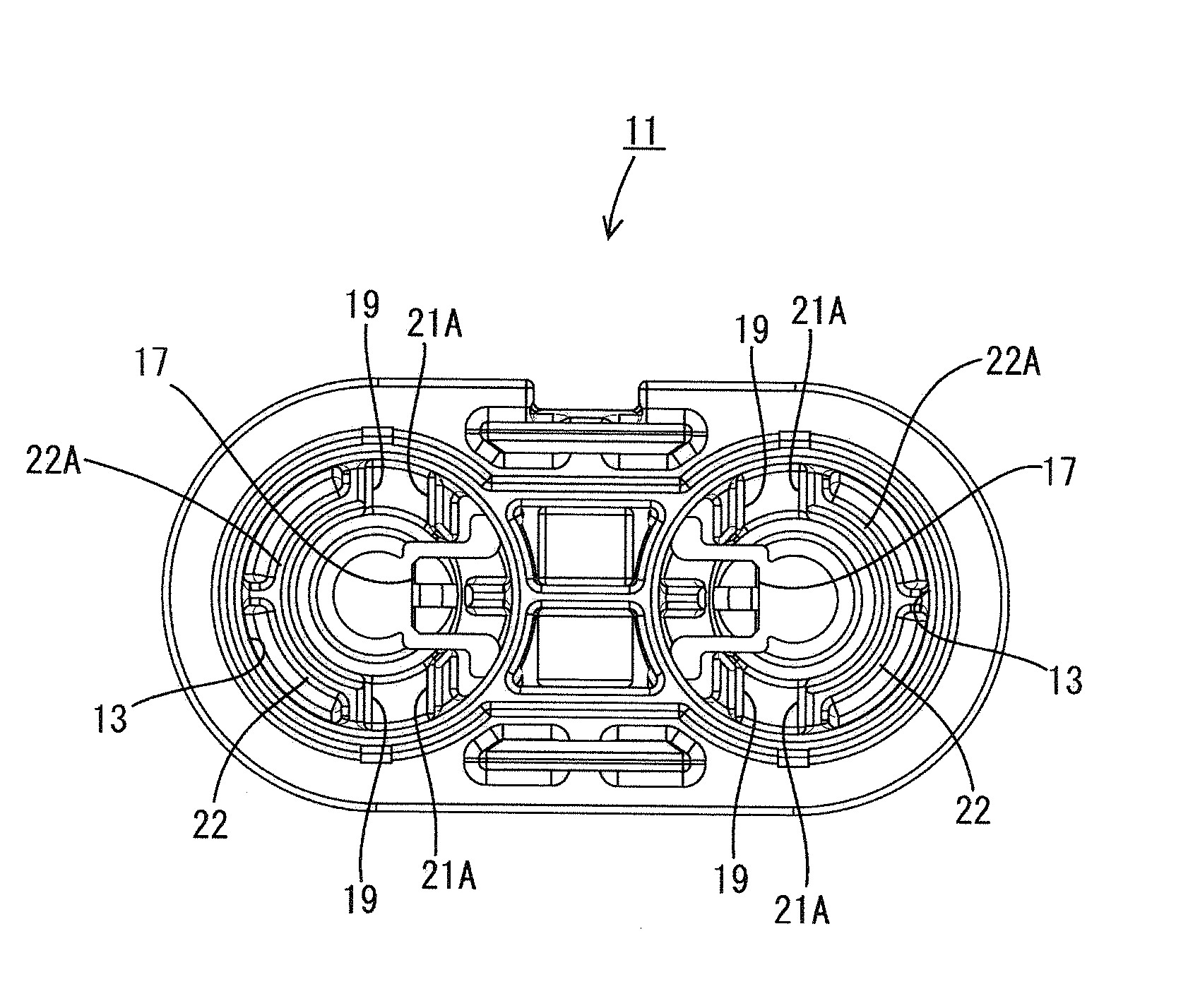
Figure 1 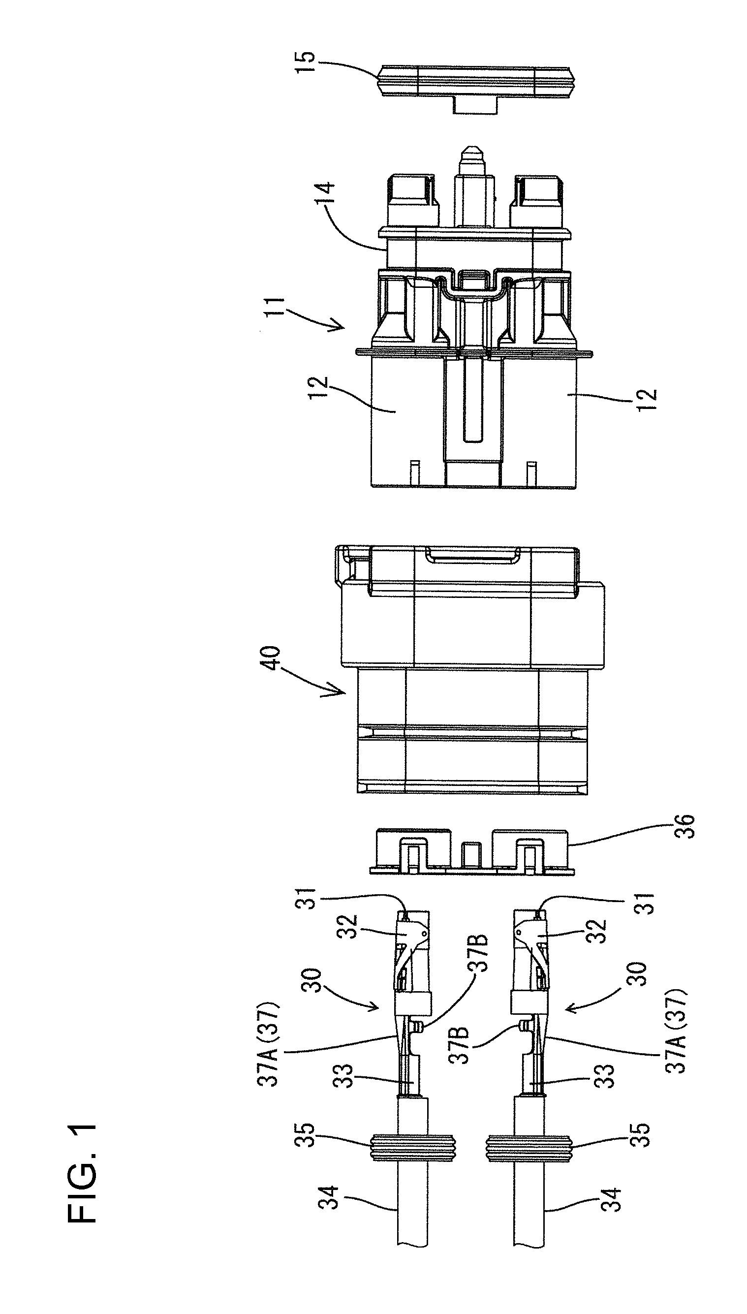
Figure 2 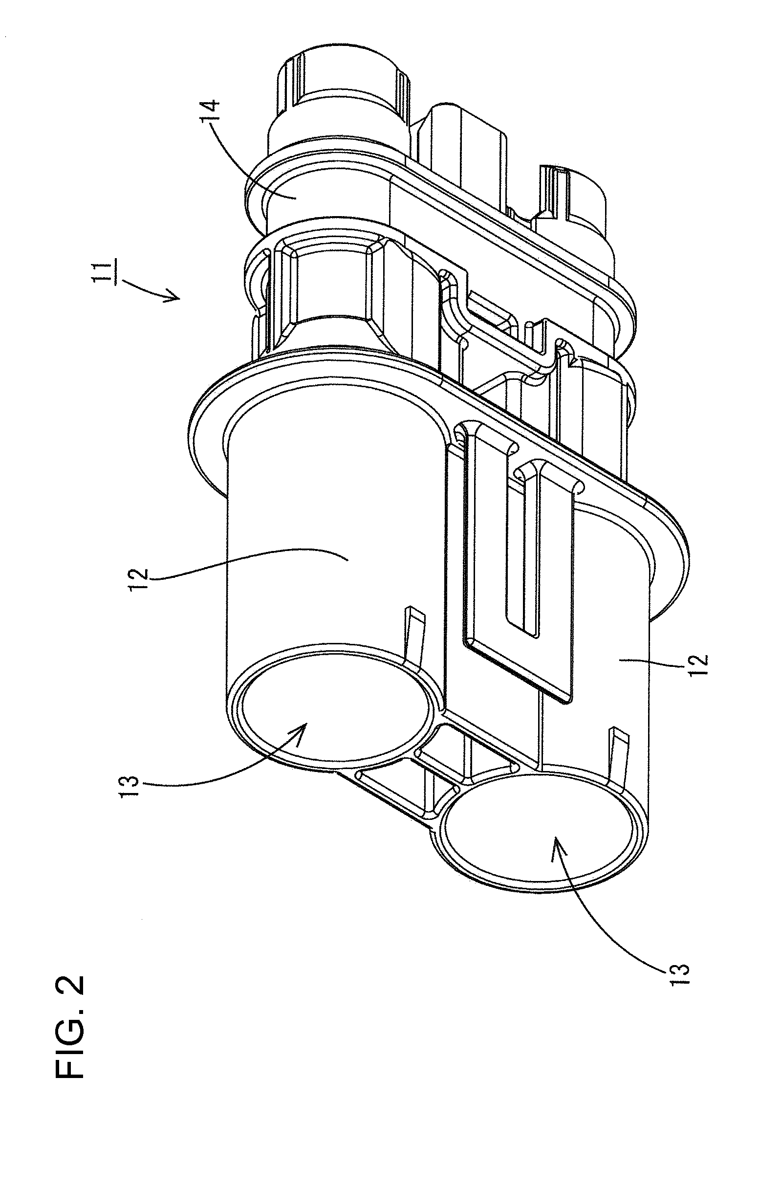
Figure 3
Abstract
Description
BACKGROUND OF THE INVENTION
[0001] 1. Field of the Invention
[0002] The invention relates to a connector.
[0003] 2. Description of the Related Art
[0004] Hybrid cars and electric cars have an inverter and a battery that are connected to each other by a power electric wire that has connectors at respective ends thereof. Each connector has a terminal fitting connected with the end of the electric wire. The terminal fitting is inserted into the insertion hole or cavity of a connector housing. A lance projects radially from the periphery of the terminal fitting and is locked to the end surface of a hole formed orthogonally to the insertion hole.
[0005] The terminal fitting should be inserted into the cavity in a normal posture. However, there is a fear that the terminal fitting can be accommodated inside the cavity in an erroneous posture (e.g. inverted) and hence the lance will not lock to the hole in the cavity.
[0006] The invention has been completed in view of the above-described situation. Thu...
Examples
Embodiment Construction
[0025]A connector in accordance with the invention is identified by the numeral 10 in FIG. 8. The connector 10 is mounted on a car, such as a hybrid car or an electric car, and is disposed on a path for supplying an electric power between a battery and equipment, such as an inverter. The connector 10 is a female connector that can be fit on a mating male connector (not shown) fixed to a case of the equipment. In the following description, the left side in FIG. 1 is the front, whereas the right side is the rear. The vertical direction and the left-to-right direction correspond to the orientation of FIG. 7.
[0026]As shown in FIG. 1, the connector 10 has a housing 11 made of a synthetic resin, a terminal fitting 30 held by the housing 11, and a die-cast aluminum shielding shell 40 fit on the housing 11.
[0027]The housing 11 has two laterally spaced terminal fitting holding parts 12, 12, integral with each other and spaced at a predetermined distance. A cavity 13 is formed inside each ter...