
Plate heat exchanger
a heat exchanger and plate technology, applied in the direction of reinforcement means, lighting and heating apparatus, laminated elements, etc., can solve the problems and reducing the efficiency of the plate heat exchanger. , to achieve the effect of reducing the stress in the reinforcement joints and facilitating bonding
Patent Information
- Authority / Receiving Office
- US · United States
- Patent Type
- Applications(United States)
- Current Assignee / Owner
- Publication Date
- 2015-03-19
- Estimated Expiration
- Not applicable · inactive patent
Smart Images
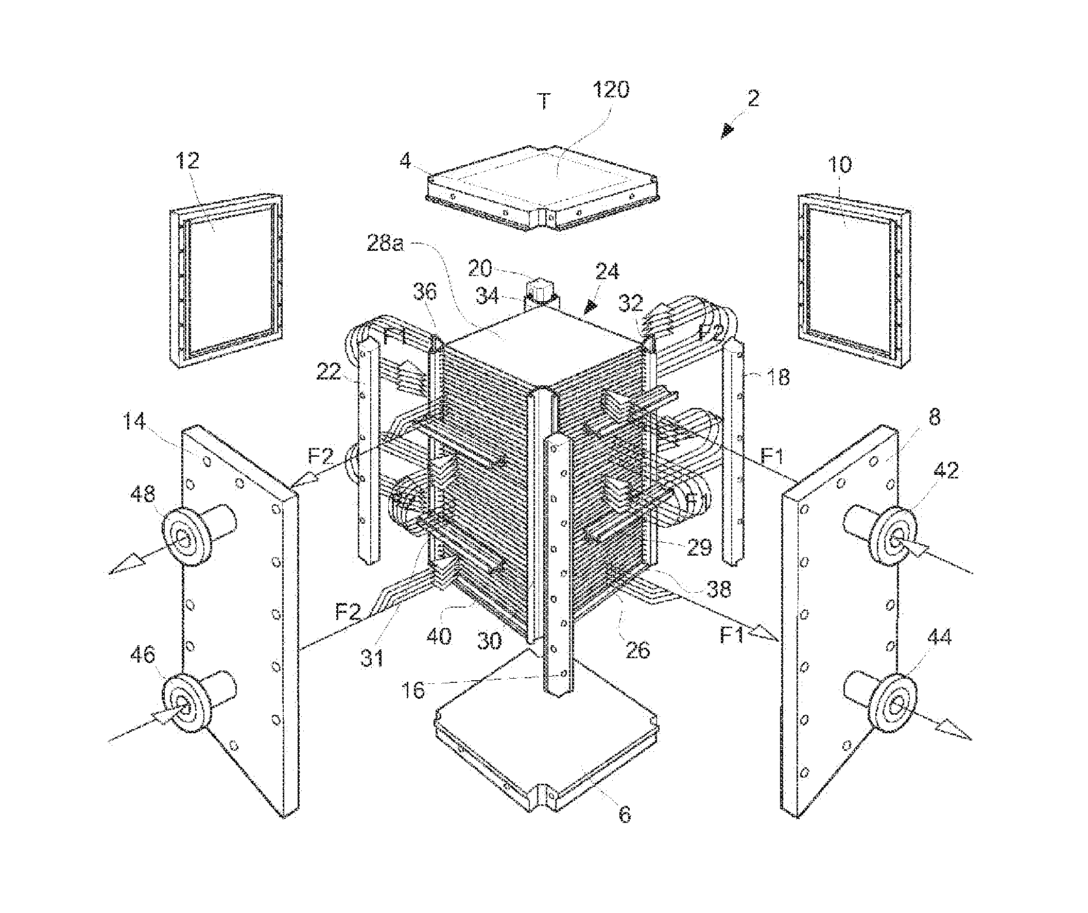
Figure 1 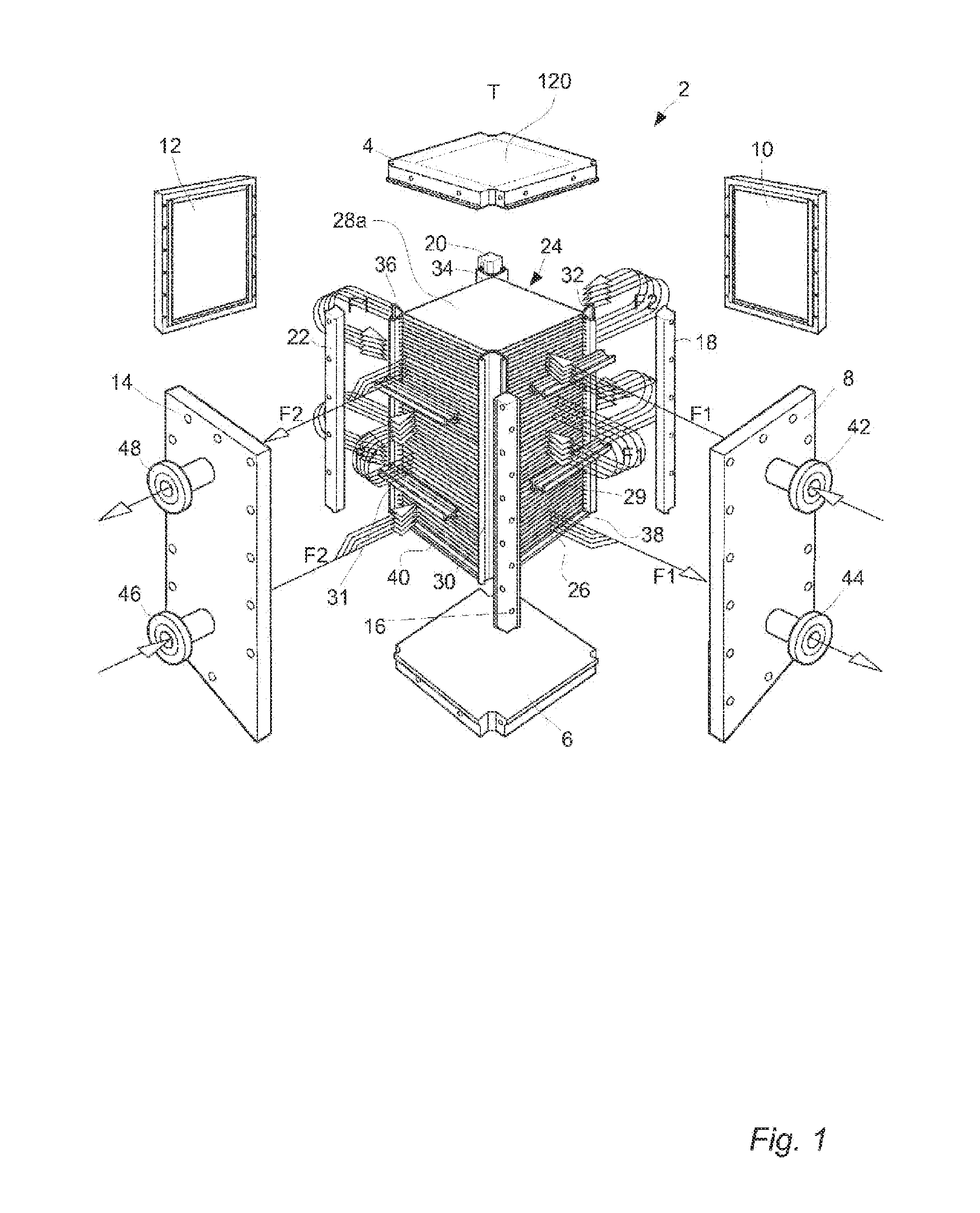
Figure 2 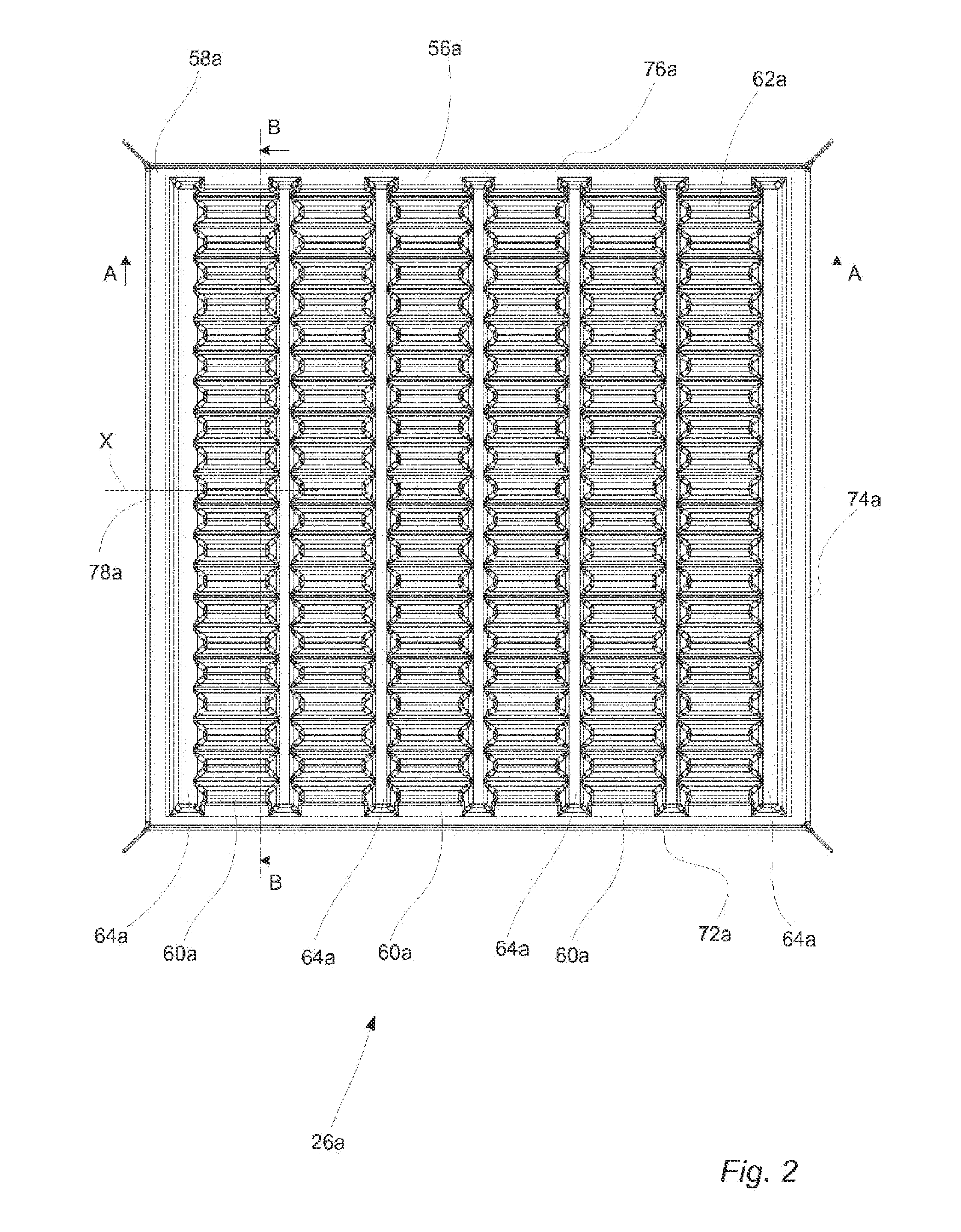
Figure 3
Abstract
Description
TECHNICAL FIELD
[0001] The invention relates to a plate heat exchanger comprising a first frame plate, a second frame plate and a stack of heat transfer plates. The heat transfer plates each have a center portion and a peripheral portion encircling the center portion. Further, the heat transfer plates are arranged in pairs between the first and the second frame plate, a first flow path for a first fluid being formed between the heat transfer plates of the pairs and a second flow path for a second fluid being formed between the pairs of heat transfer plates. One of the first and second flow paths is a free-flow path along which the center portions of the heat transfer plates are completely separated from each other.BACKGROUND ART
[0002] Today several different types of plate heat exchangers exist, which are employed in various applications depending on their type. One certain type of plate heat exchanger is assembled by bolting a top head, a bottom head and four side panels to a set of c...
Examples
Embodiment Construction
[0048]With reference to FIG. 1 a plate heat exchanger 2 of a block-type is shown. The plate heat exchanger 2 comprises a first frame plate or top head 4, a second frame plate or bottom head 6 and four side panels 8, 10, 12 and 14 that are bolted together with four corner girders 16, 18, 20 and 22 to form a parallelepiped shaped enclosure of the assembled plate heat exchanger 2. A stack 24 of aligned essentially rectangular heat transfer plates 26 of stainless steel and two rectangular reinforcement plates 28 of stainless steel (of which only one denoted 28a can be seen in FIG. 1) are arranged within the enclosure. The reinforcement plates 28 are aligned with the heat transfer plates 26 and attached to a respective end of the stack 24. Conventional baffles 29 and 31 are connected to sides of the stack 24 of heat transfer plates 26. The heat transfer plates, reinforcement plates and baffles will be further discussed below.
[0049]Four side linings 30, 32, 34 and 36 arranged to face a re...