
Pneumatic Tire
a pneumatic tire and tread technology, applied in the field of pneumatic tires, can solve the problems of reduced rigidity of the tread portion, decreased drainage performance, and decreased steering stability on dry road surfaces, so as to improve steering stability, enhance wet performance, and ensure steering stability
Patent Information
- Authority / Receiving Office
- US · United States
- Current Assignee / Owner
- Publication Date
- 2018-07-26
Smart Images
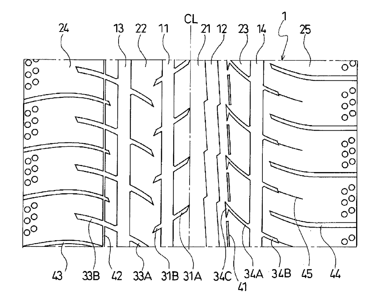
Figure 1 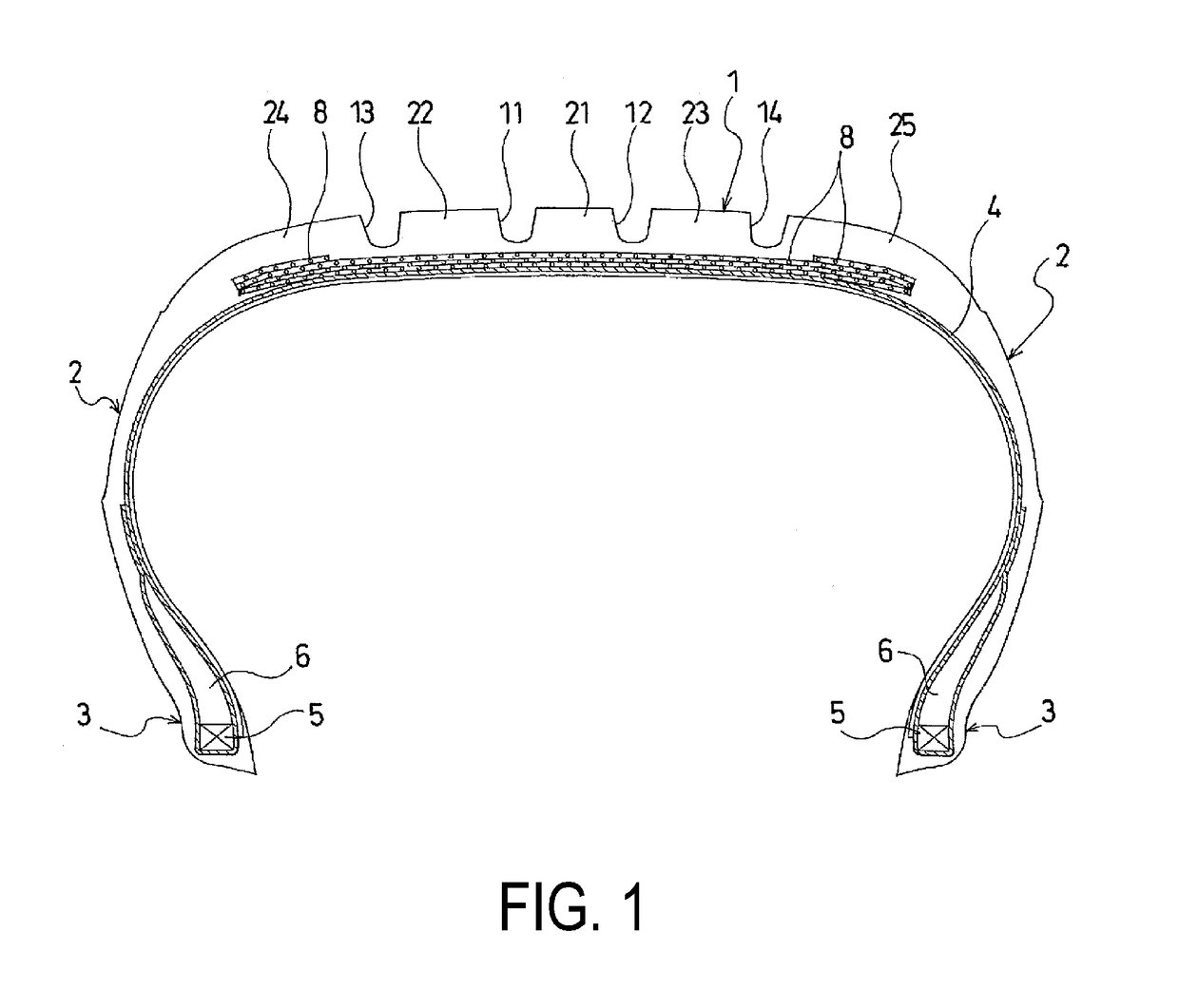
Figure 2 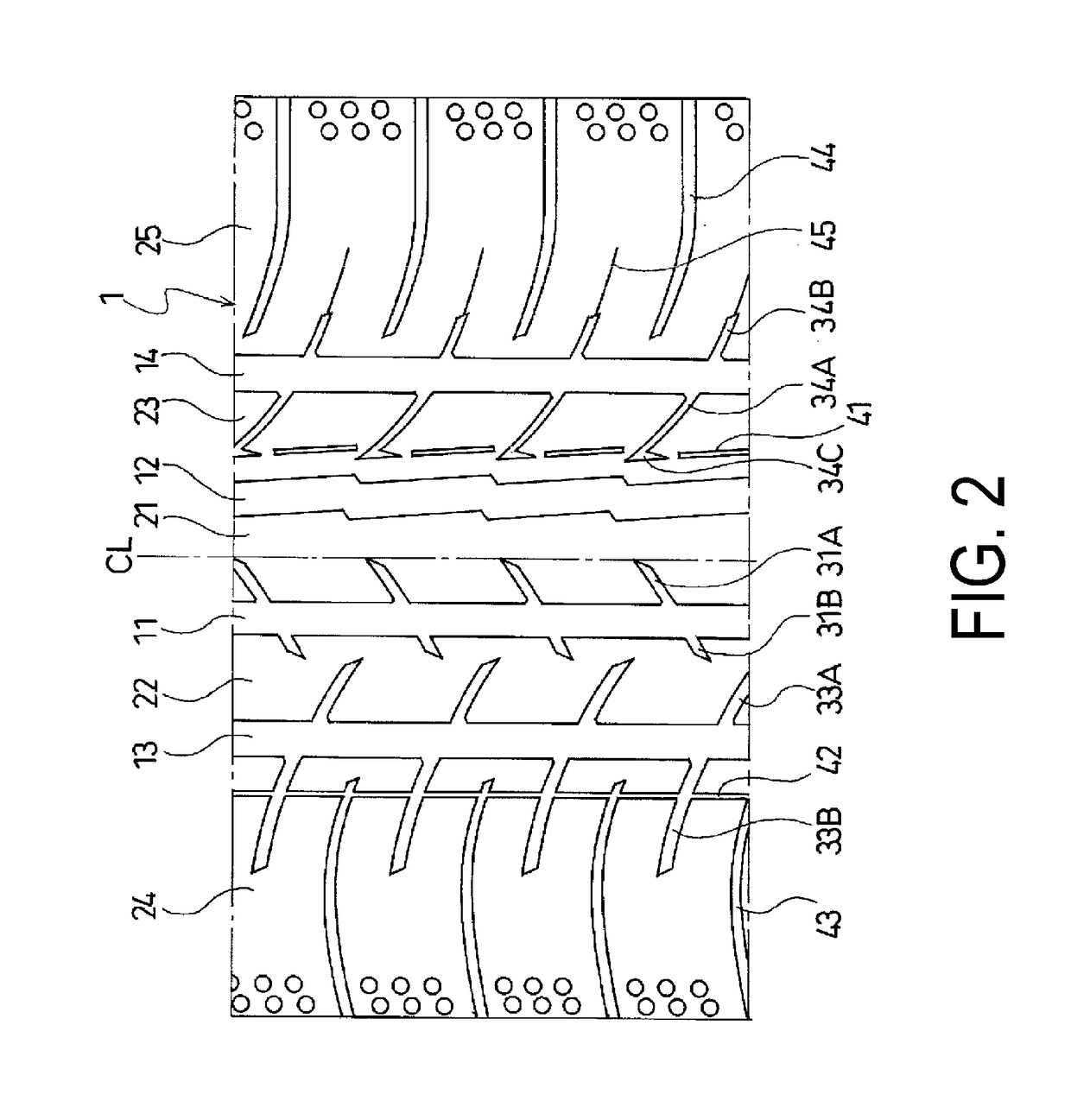
Figure 3
Abstract
Description
TECHNICAL FIELD
[0001] The present technology relates to a pneumatic tire including a tread portion including a center main groove extending in the tire circumferential direction, shoulder main grooves located outward of the center main groove and extending in the tire circumferential direction, and land portions extending in the tire circumferential direction defined between the center main groove and the shoulder main grooves; and particularly relates to a pneumatic tire including a tread pattern with an appropriate configuration that can achieve good steering stability on dry road surfaces and steering stability on wet road surfaces, which have a negative correlation, in a compatible manner and furthermore can provide improved uneven wear resistance.BACKGROUND ART
[0002] Pneumatic tires have a tread pattern in which a plurality of rows of land portions are defined by a plurality of main grooves disposed in a tread portion and extend in the tire circumferential direction (for example,...
Examples
examples
[0037]Tires of Examples 1 to 7 were manufactured with a tire size of 215 / 55R17. The pneumatic tires each included a tread portion, a pair of sidewall portions, and a pair of bead portions. As illustrated in FIG. 2, the pneumatic tire was provided, in the tread portion, with four main grooves including a pair of center main grooves extending in the tire circumferential direction and a pair of shoulder main grooves located outward of the center main grooves and extending in the tire circumferential direction; these main grooves defined five rows of land portions; one of the center main grooves had a zigzag shape in the tire circumferential direction, and the other main groove had a straight shape; a plurality of lug grooves extending inward from the shoulder main groove in the tire lateral direction and terminating without communicating with the center main groove were provided in the land portion located between the zigzag center main groove and the shoulder main groove; the lug groo...