
Pneumatic brake booster having a connecting pin
Patent Information
- Authority / Receiving Office
- US · United States
- Current Assignee / Owner
- Publication Date
- 2018-12-20
Smart Images
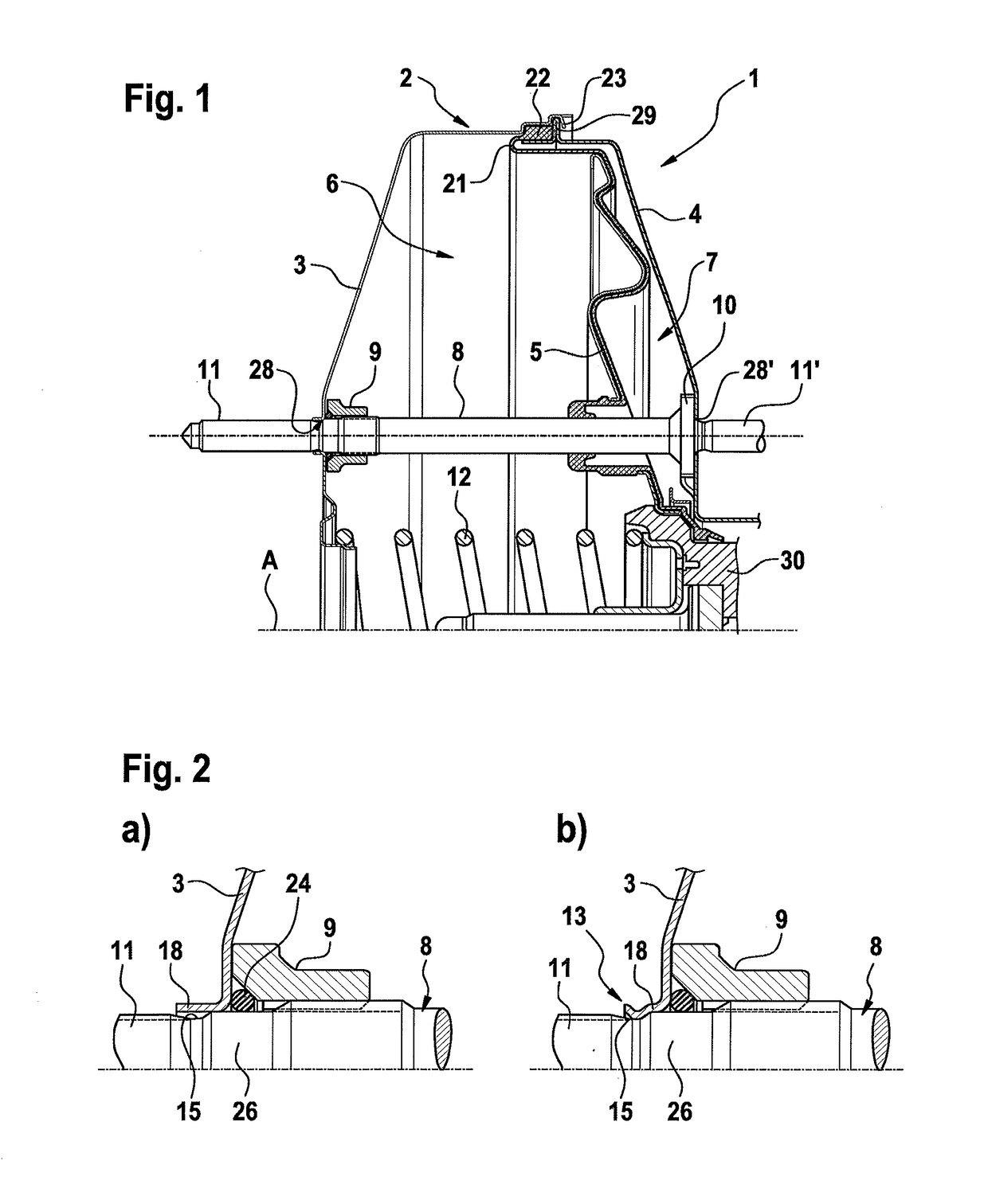
Figure 1 
Figure 2 
Figure 3
Abstract
Description
CROSS REFERENCE TO RELATED APPLICATIONS
[0001] This application is the U.S. National Phase Application of PCT International Application No. PCT / EP2016 / 064273, filed Jun. 21, 2016, which claims priority to German Patent Application No. 10 2015 212 089.9, filed Jun. 29, 2015, the contents of such applications being incorporated by reference herein.FIELD OF THE INVENTION
[0002] The invention relates to a pneumatic brake booster for a hydraulic motor vehicle brake system.BACKGROUND OF THE INVENTION
[0003] Such brake boosters are widespread and are known, for example, from WO0061416A1, which is incorporated by reference or WO2004101341A2, which is incorporated by reference.
[0004] The booster housing of such brake boosters usually comprises two cup-shaped housing shells which are arranged in series along a brake booster central axis.
[0005] Brake boosters of the generic type have connecting pins which are arranged in the booster housing in an axis-parallel fashion with respect to the central axis ...
Examples
Embodiment Construction
[0039]FIG. 1 shows a partial view of a known embodiment of a pneumatic brake booster 1 of the generic type.
[0040]The booster housing 2 comprises a front housing shell 3 and a rear housing shell 4 which are arranged in series along a central axis A. A working wall 5 is shifted to limited extent along the central axis A, which working wall separates a vacuum chamber 6 from a working chamber 7. For the purpose of sealing the vacuum chamber 6 off from the working chamber 7, a rolling diaphragm 21 is applied partially to the working wall 5. A sealing bead 22, which is clamped in axially and radially between the housing shells 3, 4 is formed onto the radial outer edge of the rolling diaphragm 21, which sealing bead 22 serves to seal the booster housing 2 with respect to the surroundings and to secure the rolling diaphragm 21.
[0041]A connecting pin 8 is arranged axis-parallel with respect to the central axis A in the booster housing 2. In the embodiment shown, the connecting pin 8 projects...