
Vibration device
a technology of vibration device and lens, which is applied in the direction of mechanical vibration separation, mounting, instruments, etc., can solve the problem that water droplets inside the field of view of the camera and attached to the lens cannot be reliably removed, and achieve the effect of reliably removing water droplets and reliable removal
Patent Information
- Authority / Receiving Office
- US · United States
- Patent Type
- Applications(United States)
- Current Assignee / Owner
- Publication Date
- 2020-02-06
Smart Images
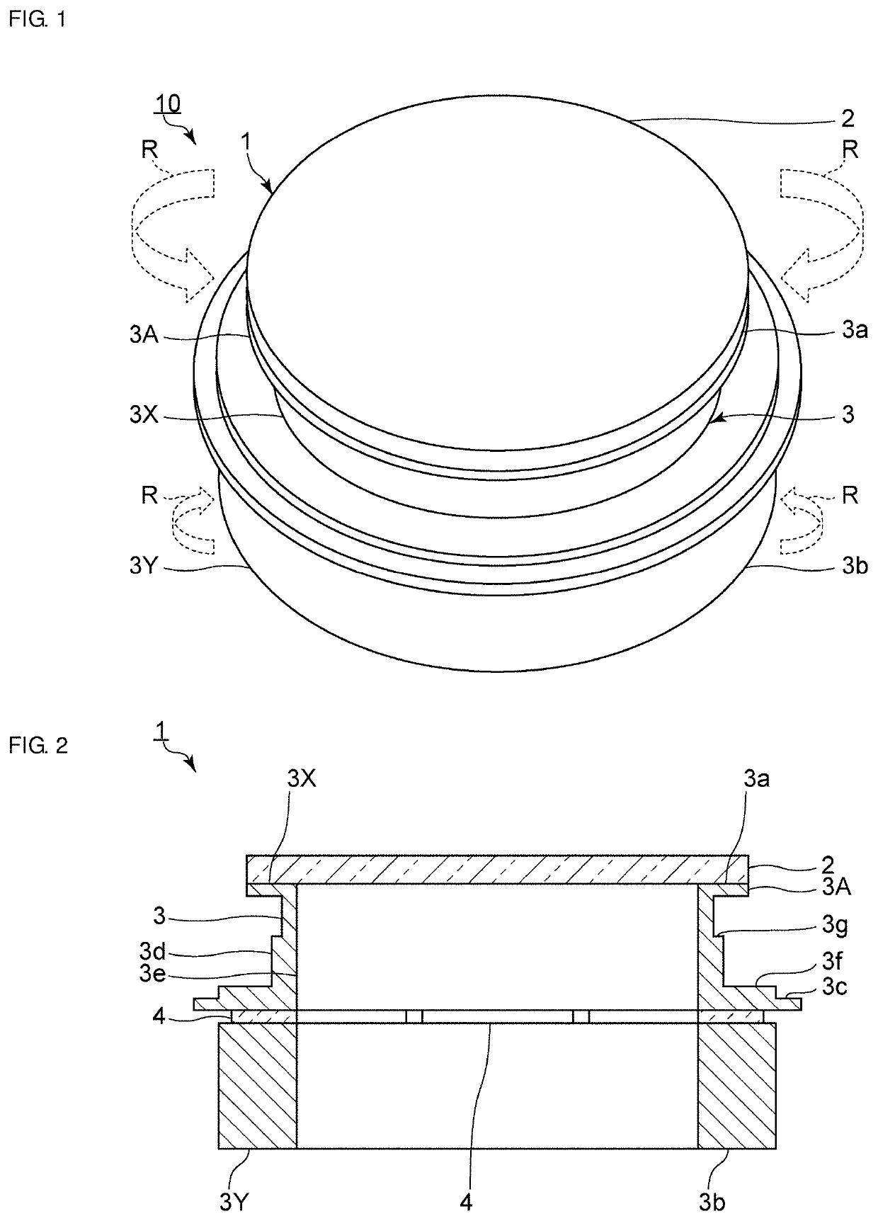
Figure 1 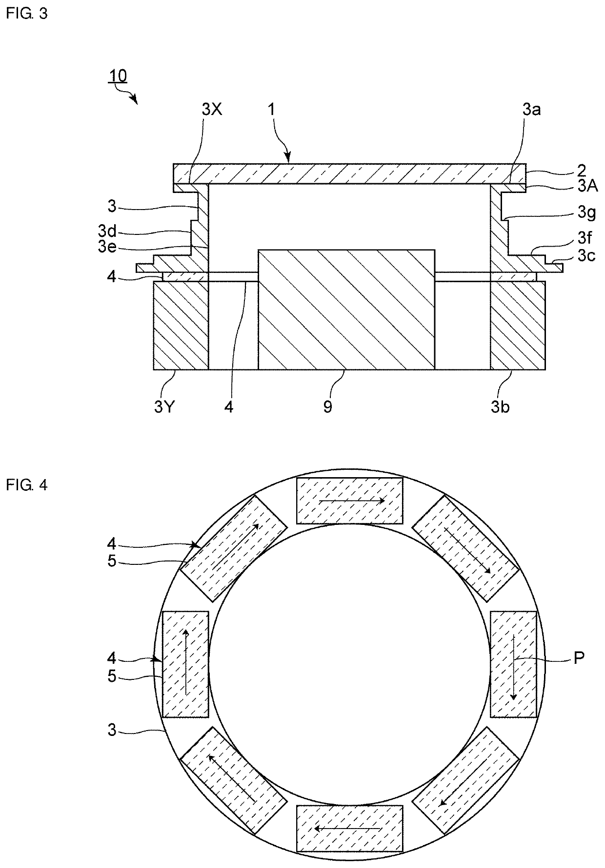
Figure 2 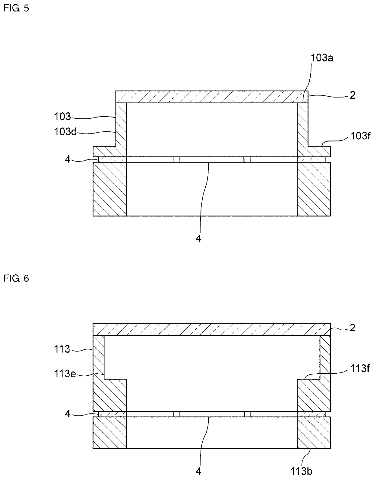
Figure 3
Abstract
Description
CROSS REFERENCE TO RELATED APPLICATIONS
[0001] This application claims the benefit of priority to Japanese Patent Application No. 2017-089410 filed on Apr. 28, 2017 and is a Continuation Application of PCT Application No. PCT / JP2017 / 044348 filed on Dec. 11, 2017. The entire contents of each application are hereby incorporated herein by reference.BACKGROUND OF THE INVENTION1. Field of the Invention
[0002] The present invention relates to a vibration device capable of removing water droplets and the like through mechanical vibration.2. Description of the Related Art
[0003] Heretofore, there has been a demand for the field of view to be always clear in imaging devices, such as cameras used as surveillance devices. In particular, various mechanisms for removing water droplets such as raindrops have been proposed for cameras used outdoors such as in automotive applications. Japanese Unexamined Patent Application Publication No. 2013-080177 discloses a camera having a water-droplet-removing fun...
Examples
Embodiment Construction
[0032]Hereafter, the present invention will be made clearer by describing specific preferred embodiments of the present invention with reference to the drawings.
[0033]The preferred embodiments described in the present specification are illustrative examples and portions of the configurations illustrated in different preferred embodiments are able to be substituted for one another or combined with one another.
[0034]FIG. 1 is a perspective view of a vibration device according to a first preferred embodiment of the present invention. FIG. 2 is a front sectional view of the vibration device according to the first preferred embodiment. FIG. 3 is a front sectional view of an imaging device that includes the vibration device of the first preferred embodiment.
[0035]As illustrated in FIGS. 1 and 2, a vibration device 1 includes a light-transmitting body 2. As illustrated in FIG. 3, in an imaging device 10, the light-transmitting body 2 is located on a subject side of an imaging element 9, th...