
Stapler
Patent Information
- Authority / Receiving Office
- US · United States
- Current Assignee / Owner
- Publication Date
- 2022-11-17
Smart Images
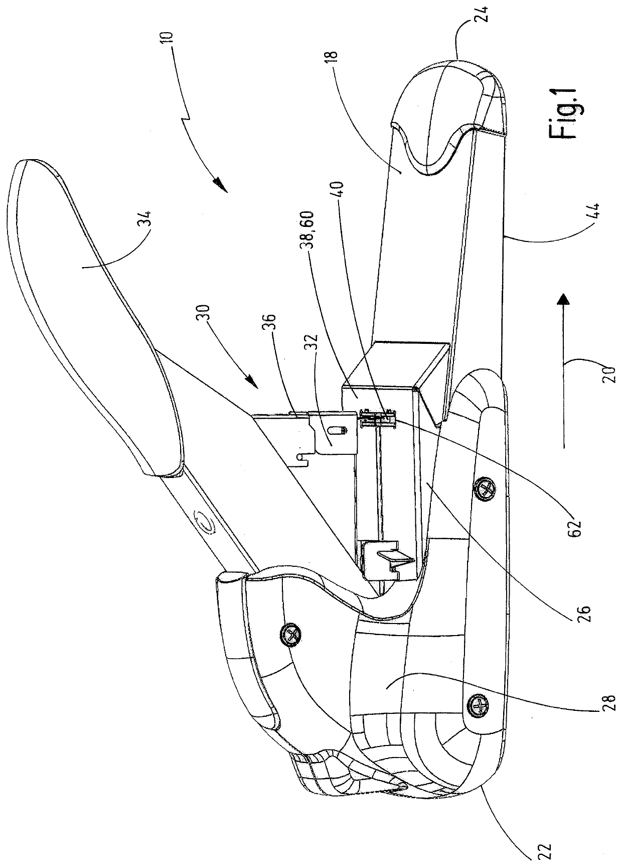
Figure 1 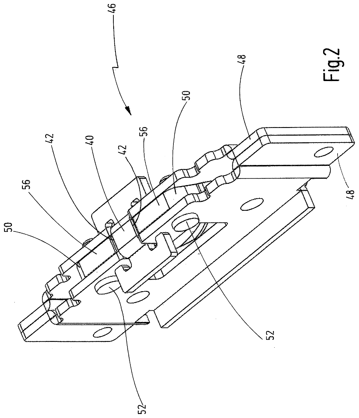
Figure 2 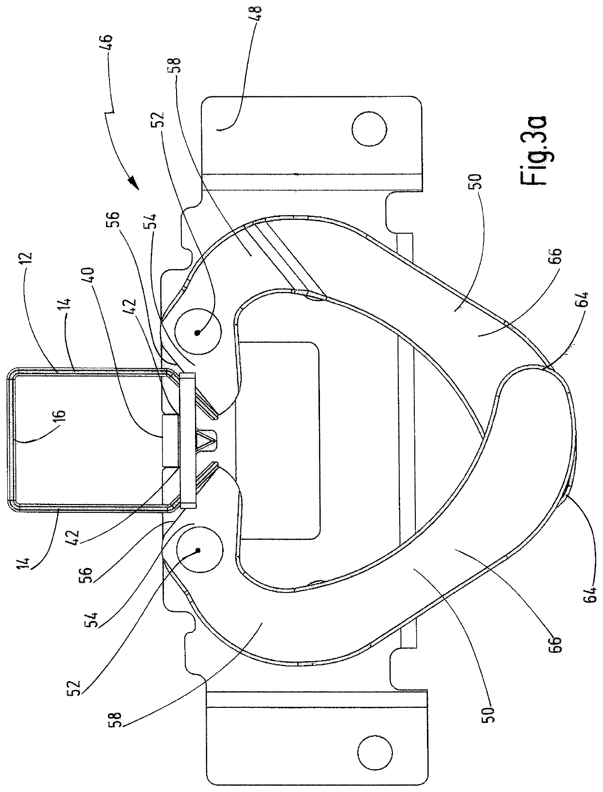
Figure 3
Abstract
Description
BACKGROUND
[0001] The invention relates to a stapler.
[0002] Such a stapler is known from EP 1 480 788 B1. The configuration thereof with an anvil arm that is movable towards a stapler base part against a restoring force and with two-armed bending levers that are pivotably mounted on the anvil arm and, when the anvil arm is pushed down, bend the staple legs that have been passed through the sheet material and cut off excess end parts of the staple legs by pressing against the cutting edges of the cutting pad makes it possible to always use the same staples for sheet material with very different total thicknesses. If only a few sheets of paper are stapled together, for the total thickness of which the staple legs are actually too long, their excess end parts are simply cut off. In order that they do not collide with one another during the bending operation, the bending levers are arranged offset to one another in a direction that extends perpendicular to the staple crowns of the staples ...
Examples
Embodiment Construction
[0015]The stapler 10 illustrated in the drawing serves to staple sheet material by means of staples 12, which, as is apparent from FIG. 3a, 3b, each have two staple legs 14 and a staple crown 16 interconnecting the staple legs 14 and extending transversely to them. The staples 12 thus have the shape of a downwardly open U, wherein during the stapling operation, the staple legs 14 pierce the sheet material with their free ends and are bent over on the underside of the sheet material.
[0016]The stapler has a base part 18, which extends in a longitudinal direction 20 from a rear end 22 to a front end 24 and bears an anvil arm 26, which is mounted on the base part 18 movably towards it against a restoring force, for example of a spring. In the present exemplary embodiment, the anvil arm 26 is mounted pivotably on the base part 18 in the region of a bearing block 28 arranged close to the rear end 22. The stapler 10 also has a stapling unit 30, which has a staple magazine 32 in which the s...