
Process and device for control and monitoring a traffic control system
a technology of traffic control system and process, applied in the direction of traffic control system, analog and hybrid computing, position/direction control, etc., can solve the problems of unjustifiable proportions, large memory requirements, and substantial increase, and achieve "superfluous" processing procedures
Patent Information
- Authority / Receiving Office
- US · United States
- Patent Type
- Patents(United States)
- Current Assignee / Owner
- Publication Date
- 2000-09-19
- Estimated Expiration
- Not applicable · inactive patent
Smart Images
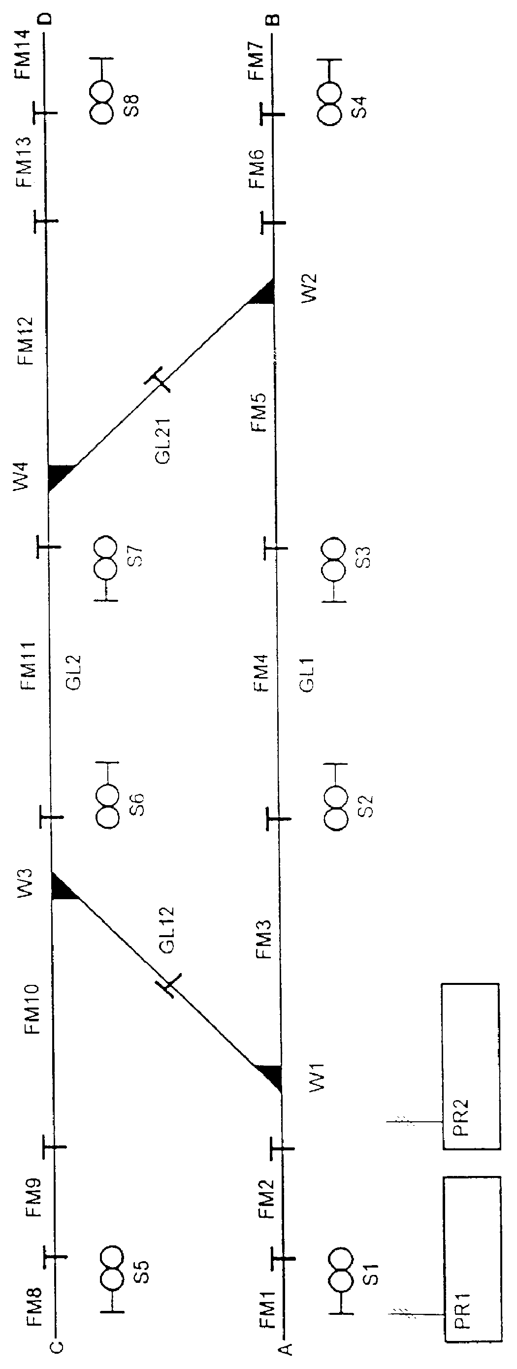
Figure 1 
Figure 2 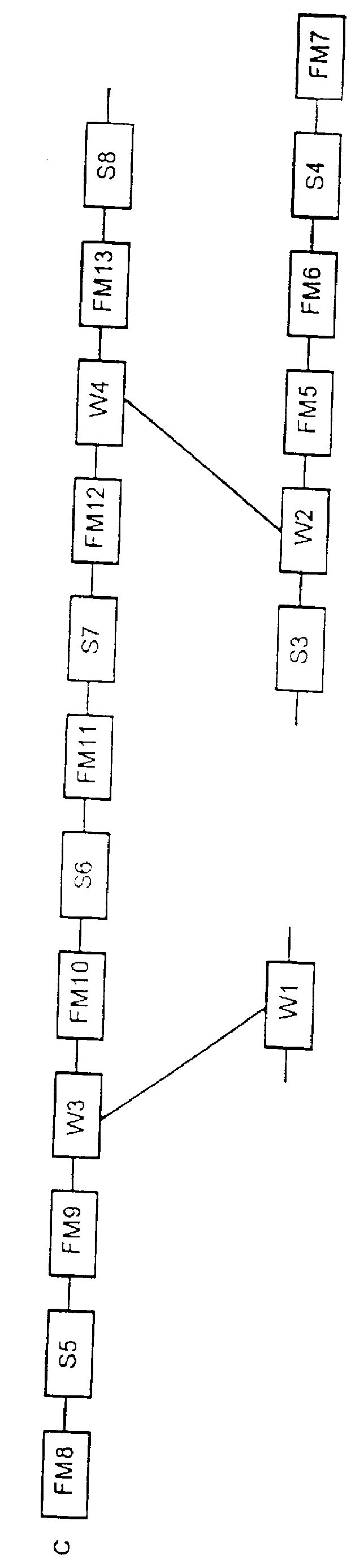
Figure 3
Abstract
Description
1. Field of the InventionThe present invention concerns a process and a device for controlling and monitoring of a traffic control system, and more particularly, to a process and device for controlling and monitoring railcars and rails therefor.2. Discussion of Background InformationVarious procedures are used in signal boxes to assign travel routes for railroad traffic. Electronic signal boxes, working in accordance with the principle of secured charts, have a memory in which all selectable routes are recorded. German Patent Application No. DE-AS 10 30 383 (see also DE-PS 35 35 785 C2, column 4, lines 38-47) describes an electronic signal box in which the target loads of all travel route segments to be included in the individual travel routes are stored in a table provided in a memory. The signal orders for the individual travel route segments are derived from the deviations between target and actual loads. This, however, entails a large memory requirement, which increases substant...
Examples
Embodiment Construction
FIG. 1 shows a railroad system with two parallel tracks GL1, GL2 going from A to B or from C to D which can be connected to one another by two connecting tracks GL12, GL21 and two switches W1, W3 or W4, W2 which are attached to each of these connecting tracks GL12, GL21. The tracks GL1, GL2 are divided into different segments, which are monitored by the clear-signal indicators FM1, . . . , FM14. The track segments around the switches W1, . . . W4 up to the middle of the corresponding connecting tracks GL12, GL21 are monitored by the clear-signal indicators FM3, FM5, FM10 and FM12. Provided following the segments associated with the clear-signal indicators FM1, FM7, FM8, and FM14 are signals S1, S4, S5, or S8. Assigned to the segments associated with the clear-signal indicators FM4 and FM11 are the signals S2 and S3 or S6 and S7.
The following travel routes can be set between points A, B, C and D, departing from point A or point C (excluding shunt routes):
Travel route 1 From A to B vi...