
Worm shaft attachment structure for spinning reel
a technology of worm shaft and attachment structure, which is applied in the field of worm shaft attachment structure, can solve the problems of difficult to ensure the difficult to maintain and difficult to form the concave hole and the through hole concentrically with high precision, so as to achieve the effect of reducing the restriction on design options and ensuring the attachment precision of the worm sha
Patent Information
- Authority / Receiving Office
- US · United States
- Current Assignee / Owner
- Publication Date
- 2005-02-22
- Estimated Expiration
- Not applicable · inactive patent
Smart Images
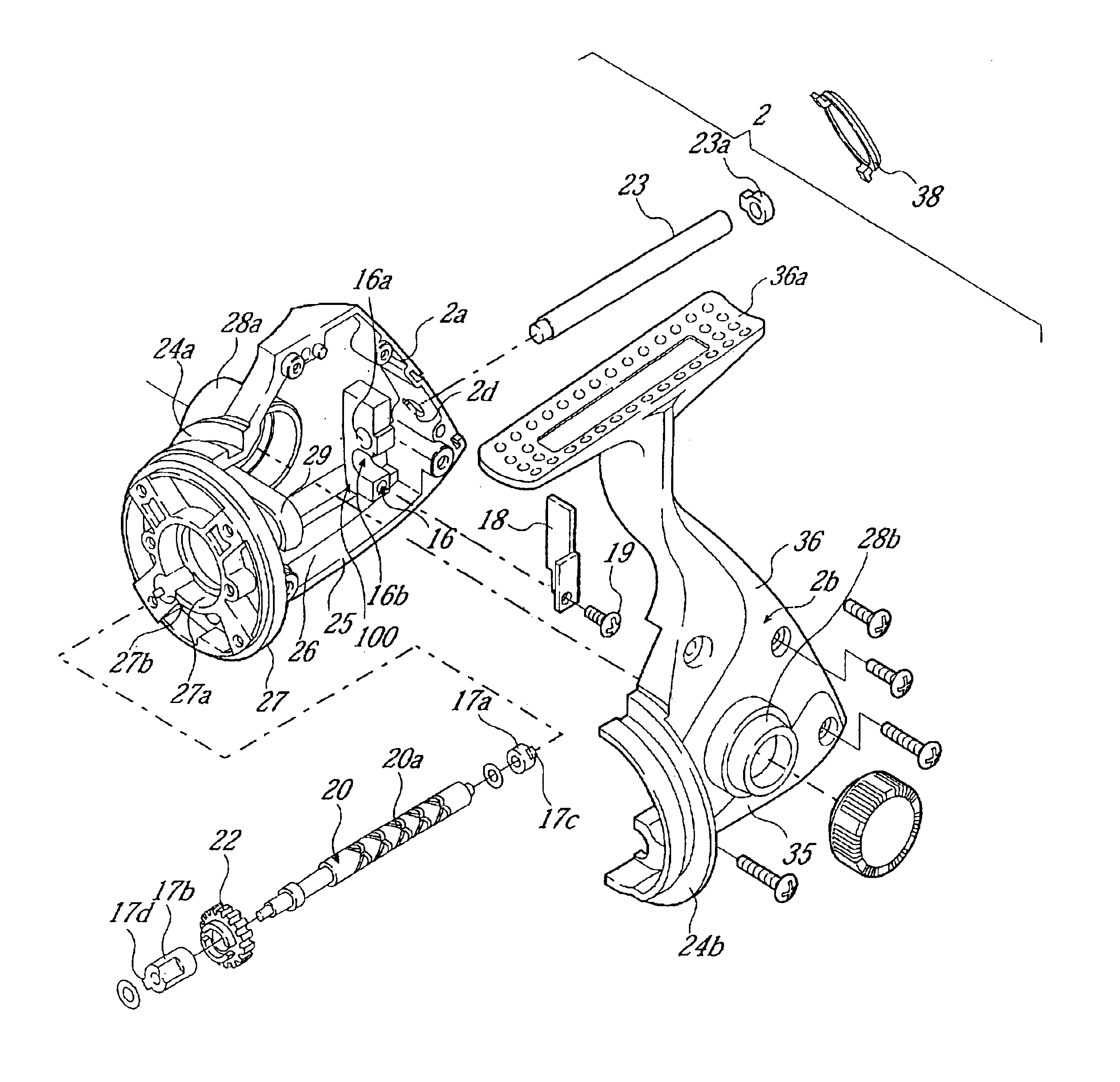
Figure 1 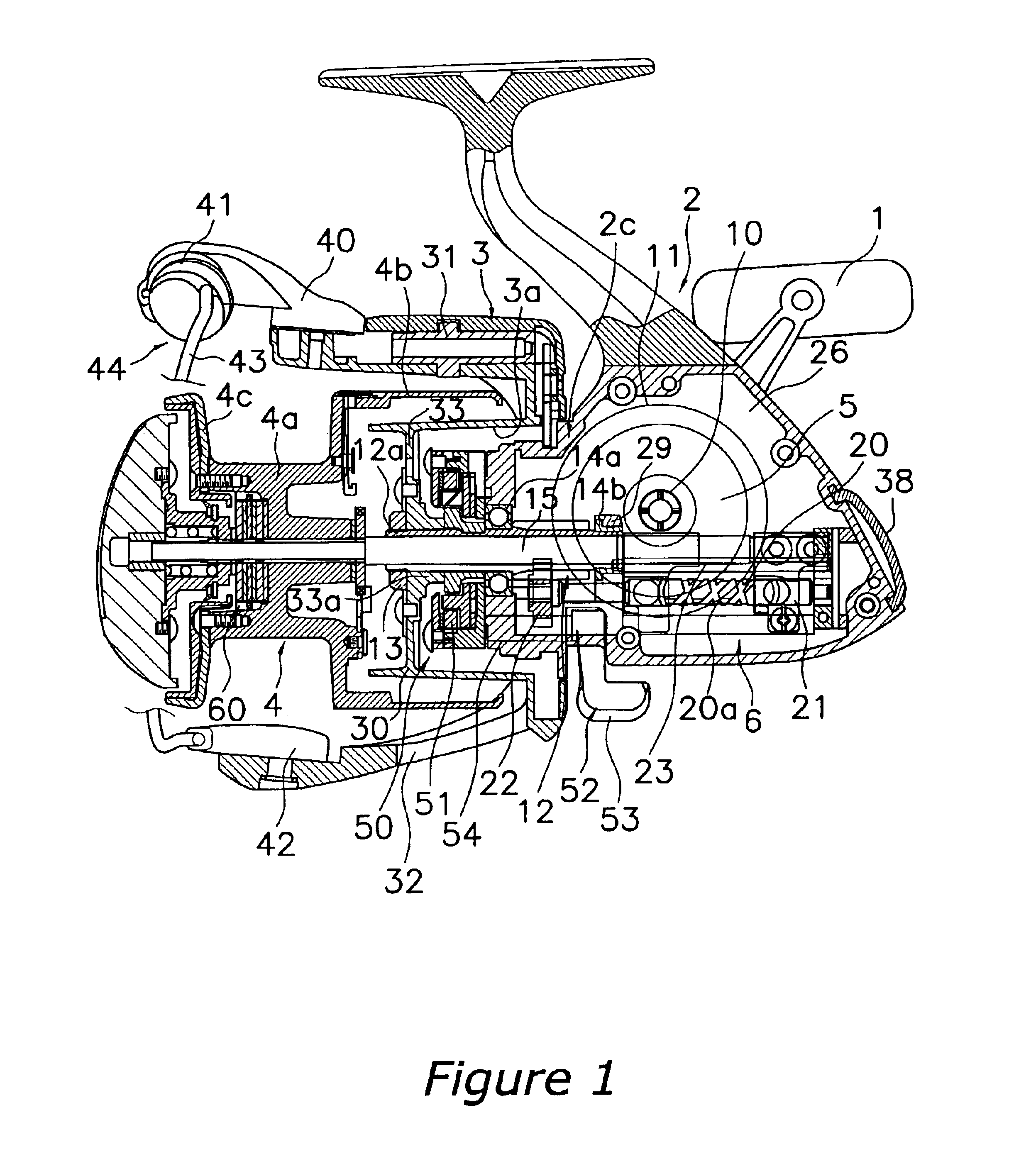
Figure 2 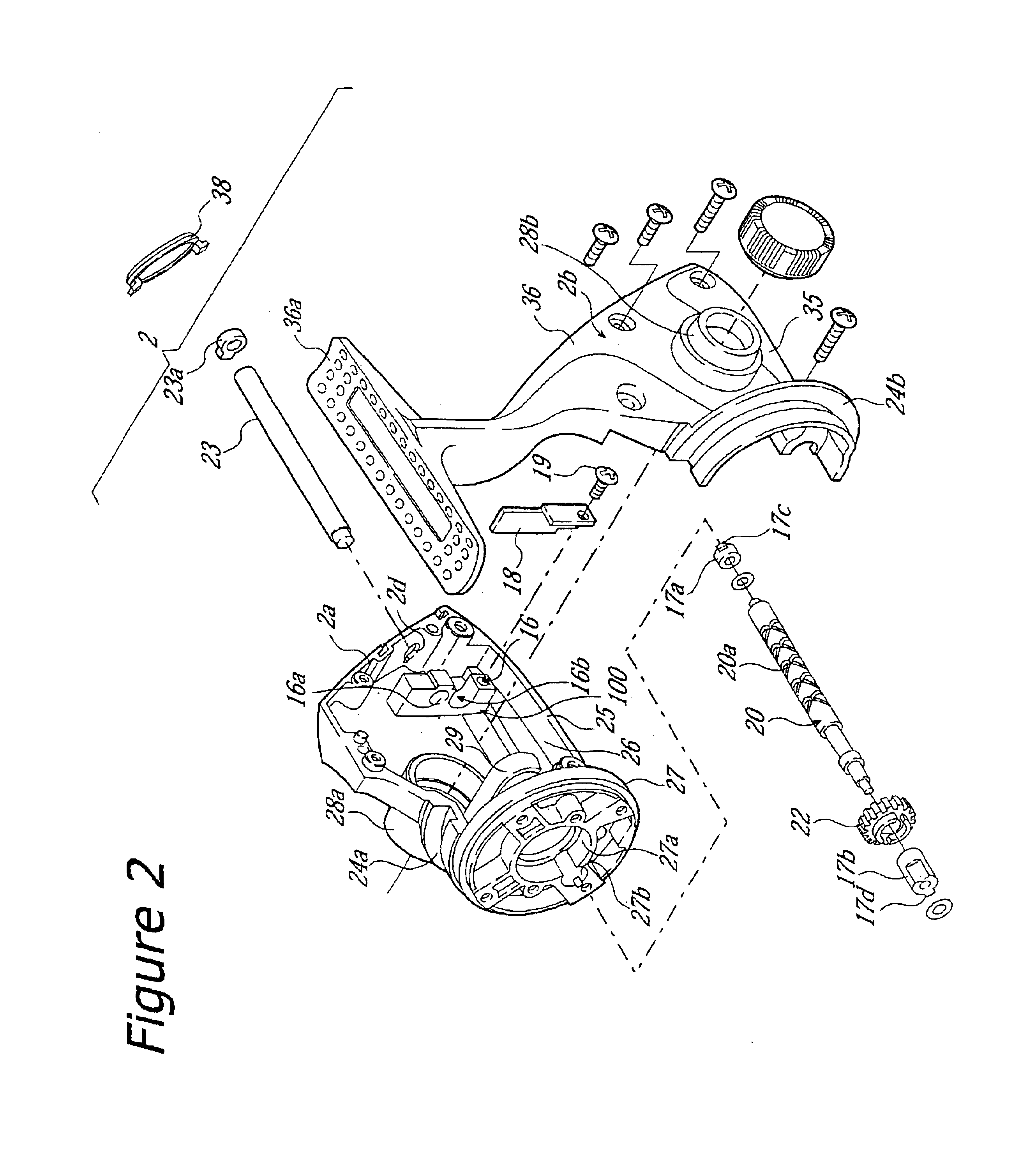
Figure 3
Abstract
Description
BACKGROUND OF THE INVENTION1. Field of the InventionThis invention generally relates to worm shaft attachment structures. More specifically, the present invention relates to worm shaft attachment structures, in which a worm shaft is attached rotatably to a reel unit via first and second bearings that are disposed at the two ends of the worm shaft, wherein intersecting helical grooves are formed on an outer circumferential surface of the worm shaft, and the worm shaft is for reciprocating a spool back and forth in cooperation with a rotation of a handle, the spool being for winding line on a spinning reel.2. Background InformationTypical spinning reels include a reel unit, a rotor rotatably supported by the reel unit, and a spool around which fishing line can be wound. The rotor has a pair of arm portions. Between the two arm portions, a bail is provided that can be switched between a line-winding posture and a line-releasing posture. Furthermore, a line roller for guiding fishing li...
Examples
Embodiment Construction
Selected embodiments of the present invention will now be explained with reference to the drawings. It will be apparent to those skilled in the art from this disclosure that the following description of the embodiments of the present invention is provided for illustration only, and not for the purpose of limiting the invention as defined by the appended claims and their equivalents.
Referring initially to FIG. 1, a spinning reel is illustrated in accordance with a first embodiment of the present invention.
As shown in FIG. 1, a spinning reel in accordance with an embodiment of the present invention is a large spinning reel, which is provided primarily with a reel unit 2 that rotatably supports a handle 1 and is to be mounted to a fishing rod, a rotor 3, a spool 4, a rotor driving mechanism 5 and an oscillation mechanism 6. The rotor 3 is for winding fishing line on the spool 4 and is supported rotatably at the front of the reel unit 2. The spool 4 is for winding fishing line around it...