
Sliding roof system for a motor vehicle
a technology for sliding roofs and motor vehicles, applied in the direction of roofs, mechanical equipment, superstructure sub-units, etc., can solve the problems of affecting the safety of passengers, and the entire sliding roof system is relatively difficult to mov
Patent Information
- Authority / Receiving Office
- US · United States
- Patent Type
- Patents(United States)
- Current Assignee / Owner
- Publication Date
- 2005-07-12
- Estimated Expiration
- Not applicable · inactive patent
Smart Images
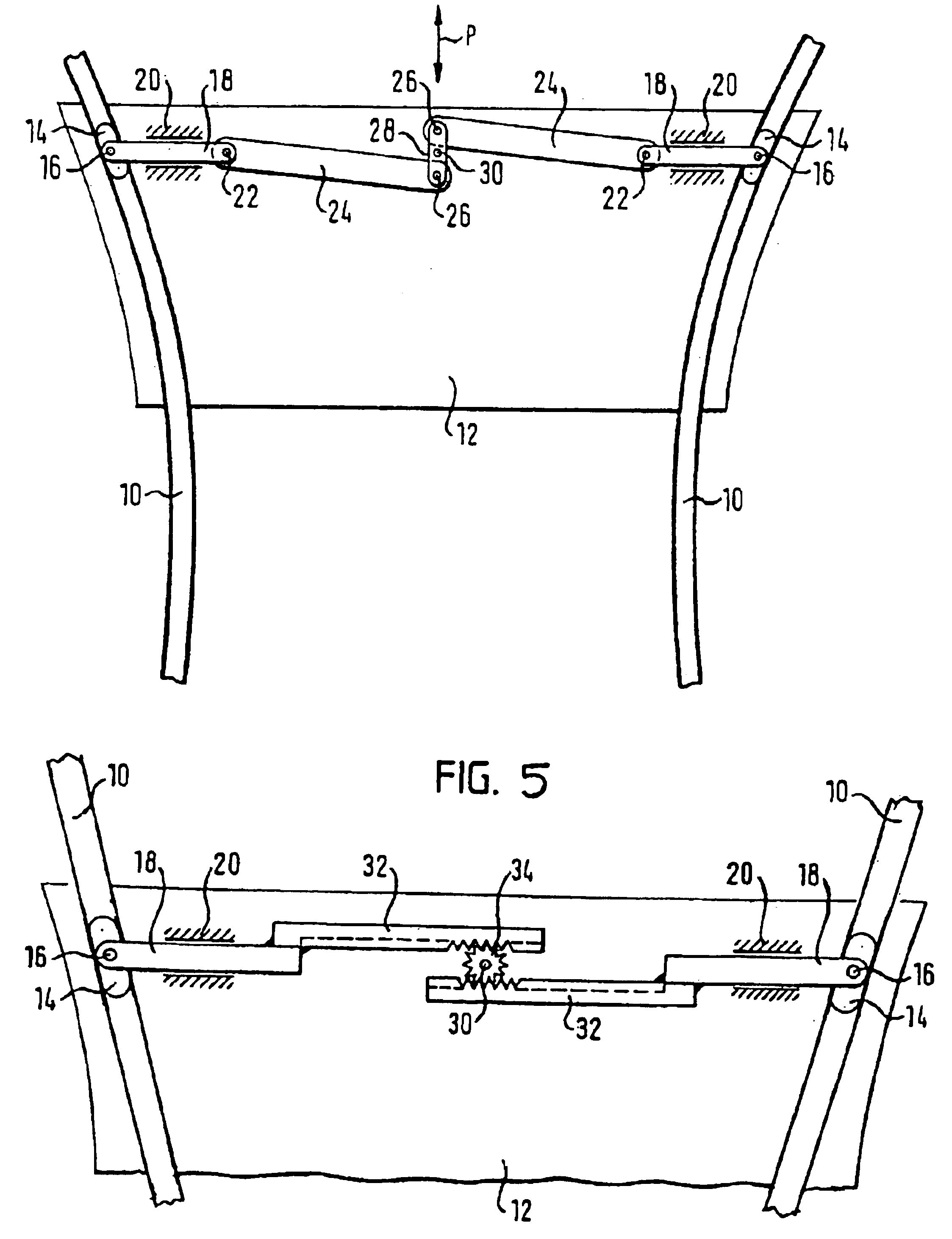
Figure 1 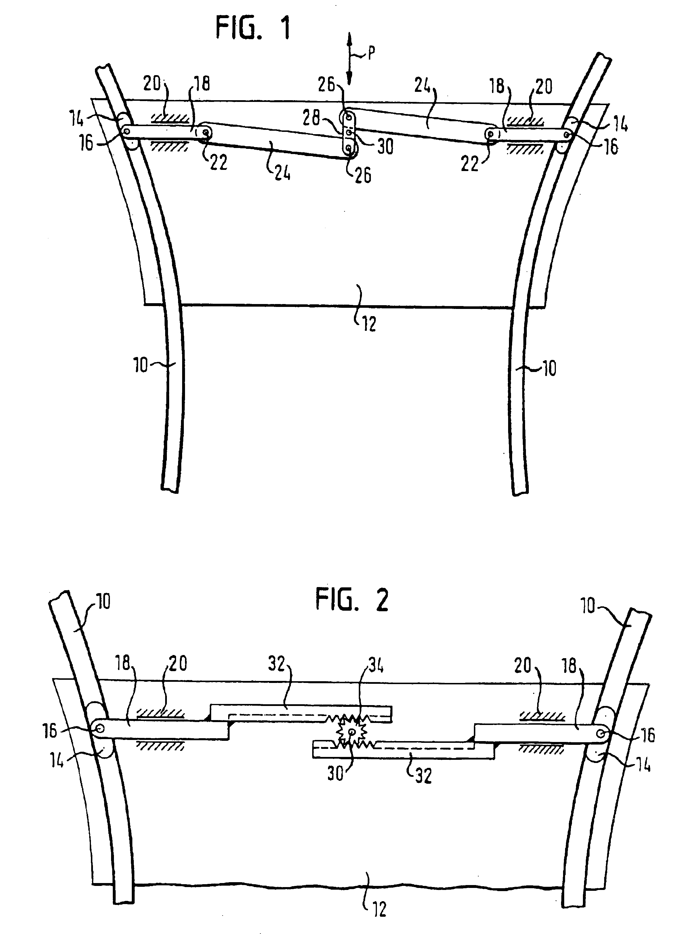
Figure 2 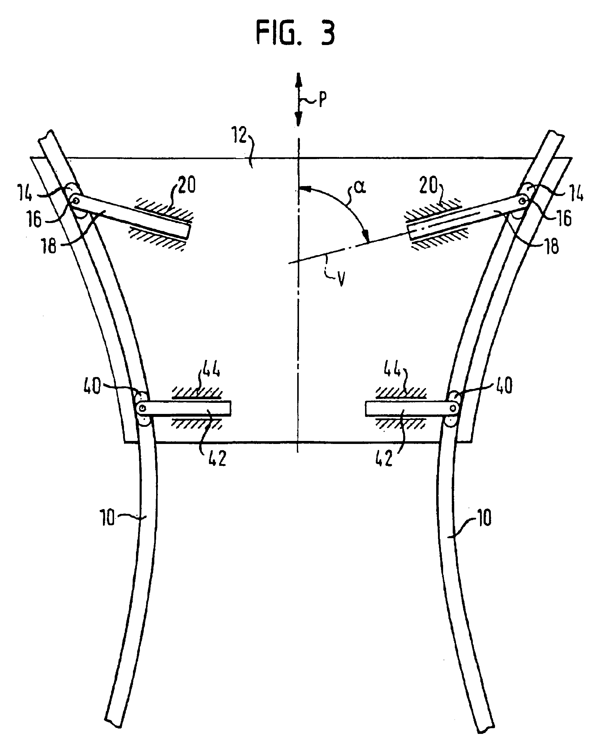
Figure 3
Abstract
Description
REFERENCE TO RELATED APPLICATIONS
[0001] The present invention claims the benefit of German Patent Application No. 102 53 401.2, filed Nov. 15, 2002.TECHNICAL FIELD
[0002] The present invention relates to a cover for a sliding roof system having at least two guide elements that are movably arranged on two opposite sides of the cover, such that the distance between them is variable. The present invention also relates to a sliding roof system having two guide tracks and to a cover of this type.BACKGROUND OF THE INVENTION
[0003] German Laid-Open Document DE 100 02 457 describes a sliding roof system that employs two straight guide tracks extending roughly in the longitudinal direction of a vehicle along the roof. The distance between the guide tracks decreases from front to back. To guide the cover in the tracks, two guide elements are provided, each of which is contained in one of the guide tracks and connected to the cover by a parallelogram guide. This makes it possible for the distance b...
Examples
first embodiment
[0022]FIG. 2 illustrates another embodiment of the inventive sliding roof system. For the components that are common with the first embodiment, the same reference numerals are used, and in this respect reference is made to the above explanations.
second embodiment
[0023]In the second embodiment, the guide bars 18 are each equipped with a toothed rack 32, which is designed as an integral part of the guide bars 18 in the illustrated embodiment. Alternatively, the toothed racks 32 may be separate components attached to their respective guide bars 18 via any known mechanism. A gear wheel 34 is rotatably mounted on a swivel axle 30 and attached to the cover 12. The toothed racks 32 are disposed so that the sides opposite each other mesh in the gear wheel 34.
[0024]A coupling mechanism configured in this manner makes it possible to adjust the distance of guide elements 14 from each other while at the same time keeping the cover 12 centered by about the swivel axis of the swivel axle 30 with respect to the guide elements 14.
third embodiment
[0025]FIG. 3 illustrates the invention. For the components that are the same as the preceding embodiments, the same reference numerals are used, and reference is made to the above explanations.
[0026]In this embodiment, the guide bars 18 of the guide elements 14 are not coupled to each other at all. Instead, the guide bars 18 can be moved freely in the sliding guides 20 attached to the cover 12. Additionally, the displacement direction V of the guide bars 18, which is predefined by the sliding guides 20, is oriented to be oblique with regard to the displacement direction P (i.e., at an angle α that is not 90°). The angle α in this example is identical for both guide bars 18; the guide bars are therefore mirror symmetrical with regard to a central axis of cover 12 that runs parallel to the displacement direction P. Alternatively, the angle α may be different for different guide bars 18, if desired.
[0027]In addition to the first pair of sliding guides and guide elements, a second, supp...